
Coupled modeling method for vibration piezoelectric energy harvesting system

A modeling method and vibration voltage technology, applied in the direction of electrical digital data processing, special data processing applications, instruments, etc., can solve the problems of high electric energy conversion efficiency, output AC voltage change, and impact on the overall conversion efficiency of the vibration piezoelectric energy harvesting system, etc. problem, to achieve the effect of simple calculation process and small amount of calculation

Active Publication Date: 2015-10-14
NAT UNIV OF DEFENSE TECH
View PDF3 Cites 16 Cited by
  • Summary
  • Abstract
  • Description
  • Claims
  • Application Information

AI Technical Summary

Problems solved by technology

However, due to the existence of the inverse piezoelectric effect of piezoelectric materials, there is a very tight coupling relationship between these parts in practice, that is, when the piezoelectric power generation structure is connected to the interface circuit, the interface circuit and the load will affect the vibration of the piezoelectric power generation structure state, and the change of the vibration state of the piezoelectric power generation structure will lead to a change in the output AC voltage, which will affect the overall conversion efficiency of the vibration piezoelectric energy harvesting system, which means that the separately optimized piezoelectric power generation structure is connected with the interface circuit Working together, the highest power conversion efficiency cannot be obtained, which is very unfavorable for practical applications

Method used


Image

  • Coupled modeling method for vibration piezoelectric energy harvesting system
  • Coupled modeling method for vibration piezoelectric energy harvesting system
  • Coupled modeling method for vibration piezoelectric energy harvesting system

Examples


Embodiment Construction

[0030] The present invention will be further described below in conjunction with the accompanying drawings and specific embodiments.

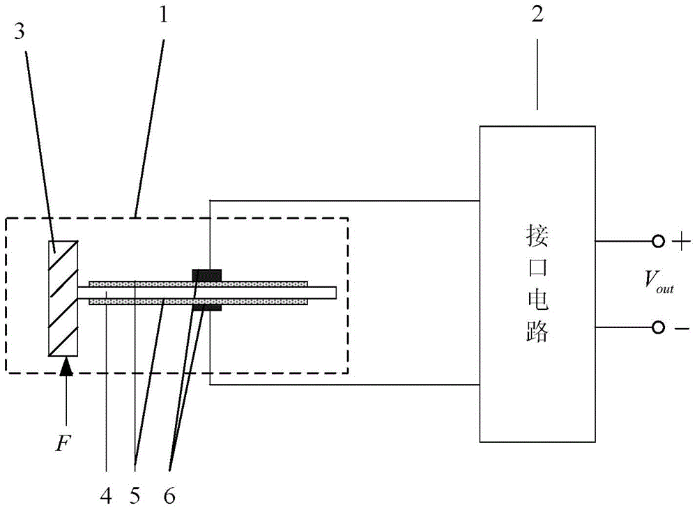
[0031] In order to facilitate the understanding of the present invention, the basic structure of the vibrating piezoelectric energy harvesting system in the prior art is firstly introduced. Such as figure 1 A structural schematic diagram of a vibrating piezoelectric energy harvesting system is shown; it includes a piezoelectric power generation structure 1 and an interface circuit 2. The piezoelectric power generation structure includes a base 3, an elastic substrate 4, a piezoelectric ceramic sheet 5 and two electrodes 6; the elastic substrate One end of 4 is clamped on the base 3 to form a cantilever beam; the piezoelectric ceramic sheet 5 is pasted on the upper and lower surfaces of the elastic substrate 4; the electrodes 6 are respectively plated on the upper and lower outer surfaces of the piezoelectric ceramic sheet 5; the interface The ...


PUM


Abstract

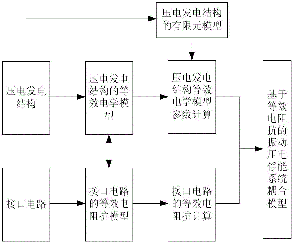
The invention belongs to the field of vibration power generation of piezoelectric materials, and discloses a coupled modeling method for a vibration piezoelectric energy harvesting system. The coupled modeling method specifically comprises the following steps of: (S1) according to an equivalent analogical relation between mechanical quantity and electrical quantity, establishing an equivalent electrical model of a piezoelectric power generation structure; (S2) establishing a finite element model of the piezoelectric power generation structure, and estimating parameters of the equivalent electrical model;(S3) enabling stray capacitance and an interface circuit of the piezoelectric power generation structure to be equivalent to electrical impedance; and (S4) connecting the equivalent electrical model of the piezoelectric power generation structure with the equivalent electrical impedance, thereby establishing a coupling model of the vibration piezoelectric energy harvesting system. The coupled modeling method has the advantages that: firstly, the coupled modeling method is suitable for a cantilever beam piezoelectric power generation structure of any shape; secondly, a computing process is simple and amount of computation is small; and thirdly, the piezoelectric power generation structure and the interface circuit can be simultaneously optimized .

Description

technical field [0001] The invention belongs to the field of vibration power generation of piezoelectric materials, in particular to a coupling modeling method of a vibration piezoelectric energy harvesting system. Background technique [0002] With the rapid development of micro-electromechanical (MEMS), low-power circuit design and other technologies, the size and power consumption of wireless sensors are getting smaller and smaller, which makes it possible to capture other energy in the environment and convert it into electrical energy to meet the working needs of wireless sensors. This eliminates the need for an external power supply or battery power. In particular, vibration energy is ubiquitous in the environment. At present, vibration energy capture can be achieved through three methods: piezoelectric, electromagnetic and electrostatic. Among them, vibration piezoelectric energy capture has received the most attention because of its high energy density. , Easy to min...

Claims


Application Information

Patent Timeline
Patent Type & Authority Applications(China)
IPC IPC(8): G06F17/50
Inventor 陈仲生程聪聪杨拥民石宏武郭彬
Owner NAT UNIV OF DEFENSE TECH
Learn More