Machining process for machining through hole in workpiece on disc machine

A processing technology and disc machine technology, applied in metal processing, metal processing equipment, drilling tool accessories, etc., can solve the problems of reducing processing efficiency, damage, increasing production and processing costs, etc., to save processing costs, improve processing efficiency, The effect of saving production and processing costs

Active Publication Date: 2015-10-21
ZHANGJIAGANG YUCHENG MASCH C0 LTD
View PDF8 Cites 1 Cited by
  • Summary
  • Abstract
  • Description
  • Claims
  • Application Information

AI Technical Summary

Problems solved by technology

However, since there is no cooling water for this kind of ordinary drill bit, it is easy to heat up and soften during the rapid drilling process, resulting in damage. This problem can only be avoided by controlling the drilling speed, which will greatly reduce the processing efficiency.
Using a spade drill can solve this problem, but the spade drill is easily damaged when drilling into and out of the irregular surface of the workpiece, thus increasing the production and processing costs

Method used


Image

  • Machining process for machining through hole in workpiece on disc machine
  • Machining process for machining through hole in workpiece on disc machine
  • Machining process for machining through hole in workpiece on disc machine

Examples


Embodiment Construction

[0017] The technical solution of the present invention will be further described below in conjunction with the accompanying drawings.

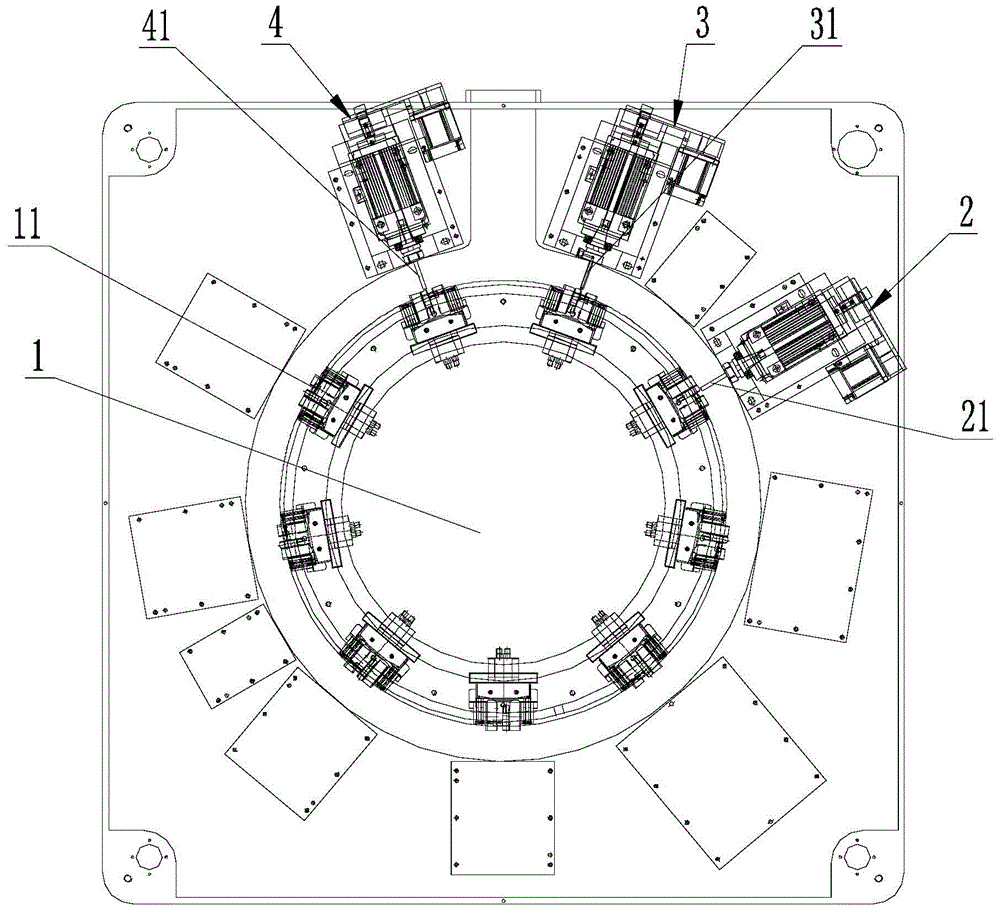
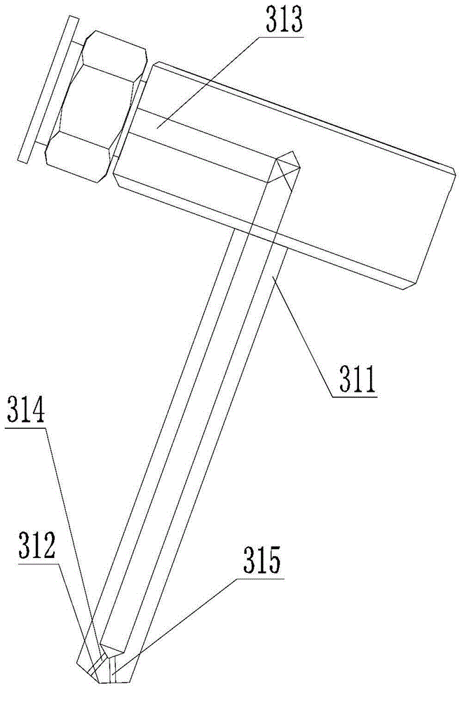
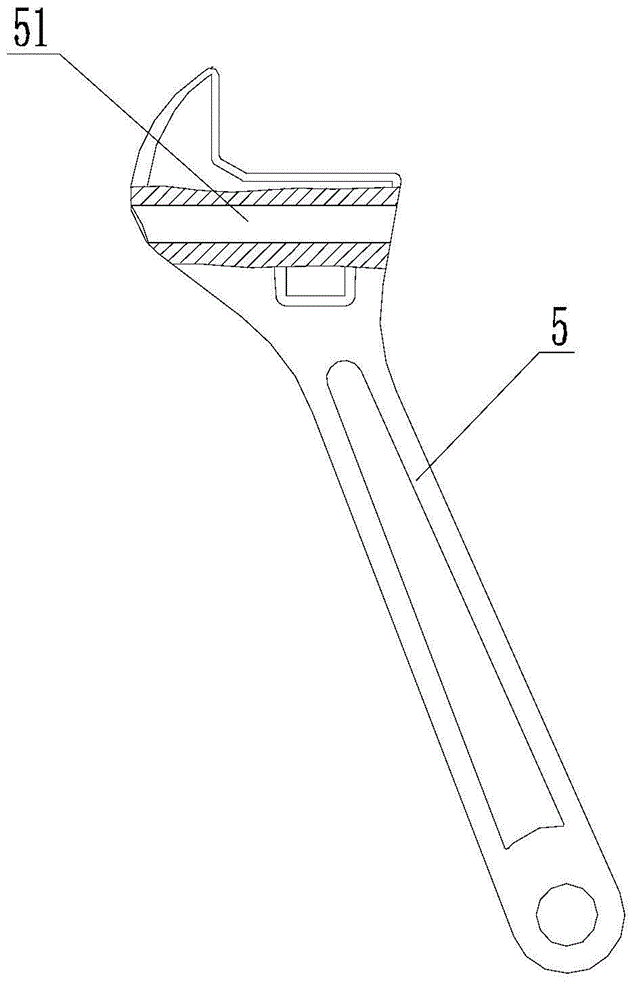
[0018] see Figure 1-3 Shown, above-mentioned a kind of processing technology that is used for the through-hole processing of workpiece on the disc machine. The disc machine includes a rotating disc 1 on a base for driving the workpiece 5 to rotate around its axis, and a processing mechanism on the base for processing the workpiece 5 . A plurality of clamping pieces 11 are evenly spaced on the outer peripheral portion of the rotating disk 1 , and the workpiece 5 is clamped on the side of the rotating disk 1 by the clamping pieces 11 and rotates together with the rotating disk 1 . The processing mechanism at least includes a first processing mechanism 2 , a second processing mechanism 3 and a third processing mechanism 4 which are arranged around the outer peripheral portion of the rotating disk 1 and distributed therebetween. In this emb...


PUM


Abstract

The invention discloses a machining process for machining a through hole in a workpiece on a disc machine. The disc machine comprises a rotary disc and a machining mechanism. The rotary disc rotates around the axis of the disc machine, and is arranged on a base and used for driving the workpiece to rotate. The machining mechanism is arranged on the base and used for machining the workpiece. The machining mechanism at least comprises a first machining mechanism body, a second machining mechanism body and a third machining mechanism body. The first machining mechanism body, the second machining mechanism body and the third machining mechanism body are arranged on the outer periphery of the rotary disc in a surrounding mode and distributed at intervals. The machining process includes the three steps of machining the through hole in the workpiece. The three machining mechanism bodies conduct preliminary hole forming, through hole body drilling and workpiece drilling-through on the workpiece respectively. An ordinary drill is adopted in hole forming positions at the two ends instead of a spade drill prone to damage when the spade drill drills in and out of the irregular surface of the workpiece, and therefore machining cost is saved. The spade drill is used for drilling a through hole body, a drill bit is cooled through a cooling water channel inside, and the through hole body can be quickly and efficiently drilled. By the adoption of the machining process, machining efficiency is improved, and meanwhile production and machining cost is saved.

Description

technical field [0001] The invention relates to a processing technology for processing a through hole of a workpiece on a disc machine. Background technique [0002] At present, the processing of the workpiece through-hole on the disc machine is generally to directly drill through the workpiece to form the required through-hole by common drill bits. However, since there is no cooling water for this kind of ordinary drill bit, it is easy to heat up and soften during the rapid drilling process, resulting in damage. This problem can only be avoided by controlling the drilling speed, which will greatly reduce the processing efficiency. This problem can be solved by using a spade drill, but the spade drill is easily damaged when drilling into and out of the irregular surface of the workpiece, thereby increasing the production and processing costs. Contents of the invention [0003] The object of the present invention is to provide a processing technology for processing through...

Claims


Application Information

Patent Timeline
IPC IPC(8): B23B39/28B23B51/00B23B51/06
CPCB23B39/28B23B51/00B23B51/06B23B35/00B23B41/02B23Q39/00
Inventor 祝析真张玉飞朱勇
Owner ZHANGJIAGANG YUCHENG MASCH C0 LTD
Why Eureka
Try Eureka