
Sealing and cutting mechanism for plastic sealing of paper money

A technology of banknotes and sealing and cutting knives, which is applied in the directions of packaging sealing/fastening, external support, transportation packaging, etc. It can solve the problems of complex structure of sealing and cutting devices, and achieve the effect of simple structure, good structure compactness and high action synchronization

Inactive Publication Date: 2015-10-21
ZHEJIANG FOTA ELECTRIC
View PDF6 Cites 6 Cited by
  • Summary
  • Abstract
  • Description
  • Claims
  • Application Information

AI Technical Summary

Problems solved by technology

[0005] The purpose of the present invention is to solve the problem that the structure of the sealing and cutting device in the existing banknote binding and plastic sealing equipment is relatively complicated, to provide a sealing and cutting mechanism driven by a mechanism such as a cam connecting rod, and to reduce the overall complexity of the sealing and cutting mechanism

Method used


Image

  • Sealing and cutting mechanism for plastic sealing of paper money
  • Sealing and cutting mechanism for plastic sealing of paper money

Examples


Embodiment Construction

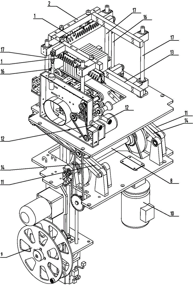
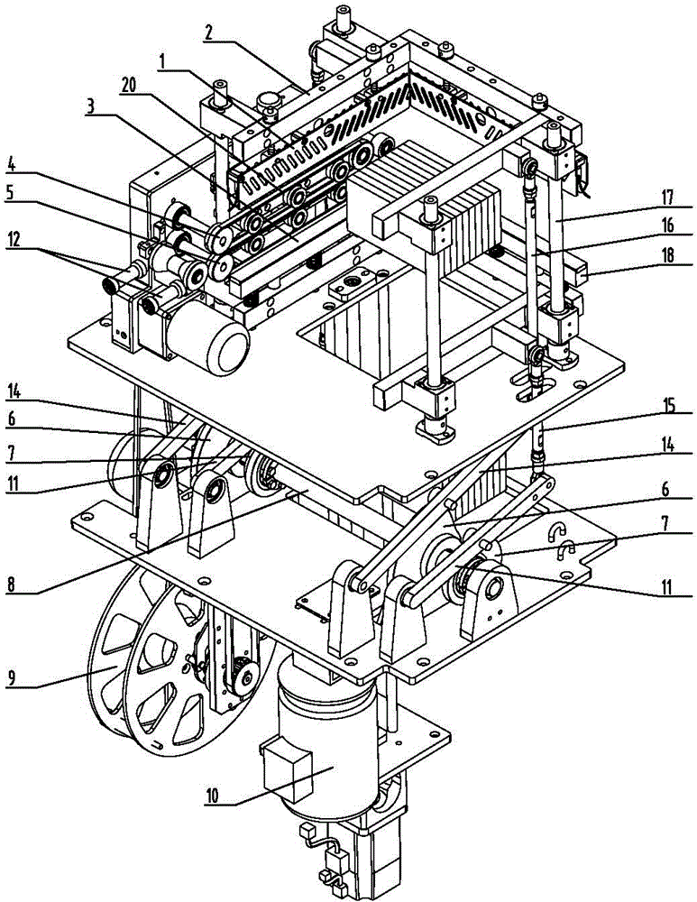
[0017] The structure and principle of the sealing and cutting mechanism of the present invention will be further described below in conjunction with the accompanying drawings.

[0018] refer to Figure 1-2 , the sealing and cutting mechanism of the present invention is mainly composed of a sealing and cutting knife group, a driving mechanism, and a waste film recycling mechanism, wherein the driving mechanism is mainly arranged under the sealing and cutting knife group, and the sealing and cutting knife group and the driving mechanism are arranged up and down, and the waste film recycling mechanism is attached The side setting of the sealing and cutting knife group and the driving mechanism.

[0019] The sealing cutter group includes an upper sealing cutter and a lower sealing cutter, the upper sealing cutter is arranged on the upper sealing cutter seat 2, the sealing cutter guard plate 1 is installed on the upper sealing cutter seat, and the lower sealing cutter 18 is arrange...


PUM


Abstract

The invention belongs to the fields of financial machines and financial tools, and discloses a sealing and cutting mechanism for plastic sealing of paper money. The sealing and cutting mechanism comprises a sealing and cutting knife group, a driving mechanism and a waste membrane recovering mechanism, wherein the sealing and cutting knife group comprises an upper sealing and cutting knife seat, an upper sealing and cutting knife, a lower sealing and cutting knife seat and a lower sealing and cutting knife, and the upper sealing and cutting knife seat and the lower sealing and cutting knife seat are respectively assembled on sealing and cutting guiding rails through sliding sleeves; the driving mechanism comprises a sealing and cutting motor, upper sealing and cutting knife driving cams, lower sealing and cutting knife driving cams, upper sealing and cutting knife driving swing rods, lower sealing and cutting knife driving swing rods, upper sealing and cutting knife driving connecting rods, lower sealing and cutting knife driving connecting rods, upper sealing and cutting knife downward pulling springs and lower sealing and cutting knife downward pulling springs; upper ends of the upper sealing and cutting knife driving connecting rods are connected with the upper sealing and cutting knife seat, and an lower end of each of the upper sealing and cutting knife driving connecting rods is hinged to each of the upper sealing and cutting knife driving swing rods; upper ends of the lower sealing and cutting knife driving connecting rods are connected with the lower sealing and cutting knife seat, and an lower end of each of the lower sealing and cutting knife driving connecting rods is hinged to each of the lower sealing and cutting knife driving swing rods; the upper sealing and cutting knife driving cams and the lower sealing and cutting knife driving cams are coaxially mounted and driven by the sealing and cutting motor in a linking manner. According to the sealing and cutting mechanism disclosed by the invention, whole bodies of all the constituent parts are arranged up and down, lateral space usage is small, and the structure is compact.

Description

technical field [0001] The invention belongs to the field of financial equipment, and relates to packaging equipment for automatic coding, bundling and automatic plastic sealing of banknotes of various denominations by a financial system. Specifically, it discloses a sealing and cutting mechanism for plastic packaging of banknotes. Background technique [0002] At present, in the process of RMB circulation, the bank's work of returning, sorting, packaging, and storing banknotes and information management is becoming increasingly heavy. The banknotes that have been sorted are bundled with paper tape every 100 bundles, and then bundled with strapping tape for every 10 bundles. In this process, manual operation is easy to cause damage and deformation to the banknotes, and cannot completely prevent the drawing of the banknotes. The banknotes will stick together, without moisture and dust protection, and even affect the service life of the banknotes, increasing the issuance cost ...

Claims


Application Information

Patent Timeline
Patent Type & Authority Applications(China)
IPC IPC(8): B65B51/14B65B61/06
CPCB65B51/146B65B61/065B65B2220/16
Inventor 黄河姜子法叶新亮
Owner ZHEJIANG FOTA ELECTRIC
Learn More