Single-drive linear motion robot

A linear motion and robot technology, applied in the direction of manipulators, program control manipulators, manufacturing tools, etc., to achieve the effect of easy integration, compact structure in the axial direction, and save space in the lateral direction

Active Publication Date: 2021-06-29
珞石(北京)科技有限公司
View PDF7 Cites 1 Cited by
  • Summary
  • Abstract
  • Description
  • Claims
  • Application Information

AI Technical Summary

Problems solved by technology

Since the slider crank mechanism cannot be separated from the frame or the extended position of the frame, it has great limitations when performing some spatial tasks

Method used


Image

  • Single-drive linear motion robot
  • Single-drive linear motion robot
  • Single-drive linear motion robot

Examples


Embodiment Construction

[0032] The following examples are used to illustrate the present invention, but are not intended to limit the scope of the present invention.

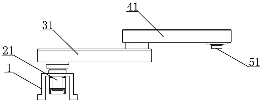
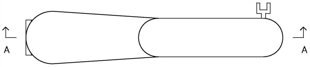
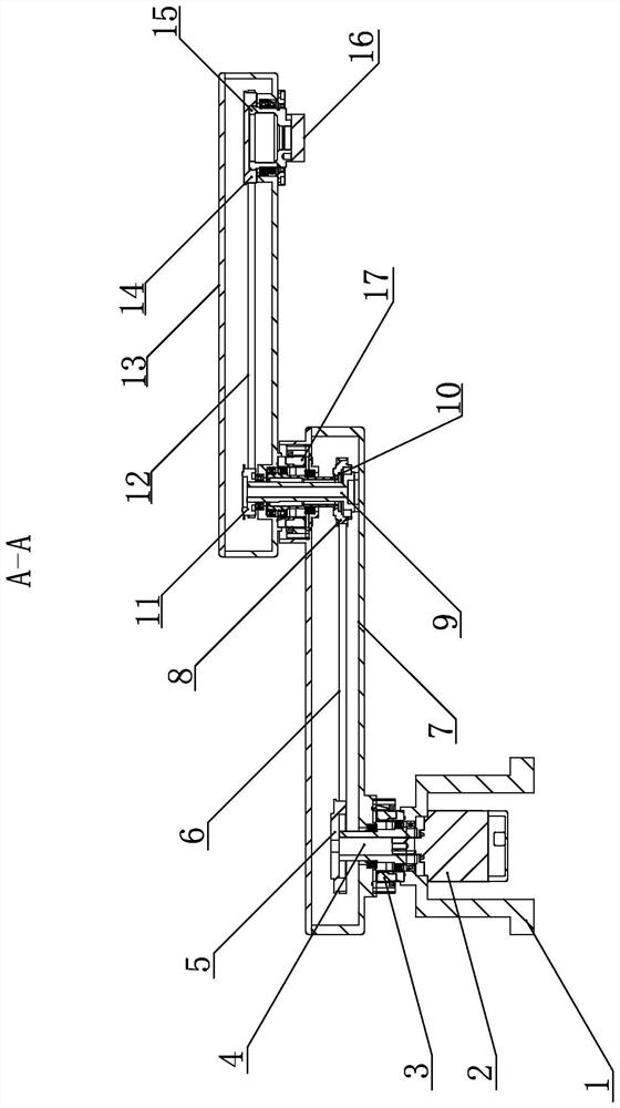
[0033] Such as Figure 1-Figure 3 As shown, the single-drive linear motion robot of the present invention includes a drive assembly 21 , a boom assembly 31 , a small arm assembly 41 and an end tool 51 .

[0034] The drive assembly 21 includes a drive motor 2 and a first reducer 3 , and the drive motor 2 and the first reducer 3 are installed on the frame 1 . The driving motor 2 drives the first transmission shaft 4 to rotate through key transmission. The first transmission shaft 4 drives the first reducer 3 to run. The output end of the first speed reducer 3 is fixedly connected with the main body 7 of the boom, so as to realize the rotation of the main body 7 of the boom.

[0035] The boom assembly 31 includes a first pulley 5 , the first pulley 5 is located inside the boom body 7 , and the first pulley 5 is driven by the first tran...


PUM


Abstract

The invention discloses a single-drive linear motion robot, and relates to an industrial robot. The single-drive linear motion robot is flexible in structure and small in occupied space. The single-drive linear motion robot comprises a driving assembly, an upper arm assembly, a forearm assembly and a tail end tool; the driving assembly comprises a driving motor, the driving motor is connected with a first transmission shaft, the first transmission shaft is connected with a first speed reducer, and the output end of the first speed reducer is connected with an upper arm body; the upper arm assembly comprises a first belt wheel, a second belt wheel and a second transmission shaft, the second transmission shaft is connected with a second speed reducer, the output end of the second speed reducer is connected with a forearm body, and a third transmission shaft is connected between the upper arm body and the forearm body; the forearm assembly comprises a third belt wheel and a fourth belt wheel, the fourth belt wheel is connected with an output shaft, and the output shaft is provided with a tool installation hole used for installing a tail end tool. The distance between the first transmission shaft and the second transmission shaft is equal to the distance between the third transmission shaft and the output shaft.

Description

technical field [0001] The invention relates to the technical field of industrial robots, in particular to a robot that uses a single drive to realize the translational movement of an end tool. Background technique [0002] The mechanism that can convert the rotational motion of the motor in the driving part into the translational motion of the actuator mainly includes: ball screw, rack and pinion, crank slider, etc. However, the use of these mechanisms in relatively harsh working conditions such as high humidity and dust flying debris has great limitations. For the ball screw and rack and pinion mechanism, due to its open structure, it is difficult to achieve absolute sealing, and the screw or rack is easily polluted by external water vapor, dust or other foreign objects; The size should be small. In some scenarios with large stroke requirements, the size of the mechanism needs to be doubled to meet it. In the slider-crank mechanism, the translational movement of the end ...

Claims


Application Information

Patent Timeline
Patent Type & Authority Applications(China)
IPC IPC(8): B25J9/04
CPCB25J9/041Y02P70/10
Inventor 张雷梁浩李振国庹华曹华韩峰涛任赜宇周祥祥
Owner 珞石(北京)科技有限公司
Why Eureka
Try Eureka