Torque extraction device

A technology of housing and input shaft, which is applied in the field of power take-off devices, can solve the problems that hydraulic automatic transmissions cannot realize power interruption, etc., and achieve the effects of high-efficiency coaxial gearless transmission, small transmission device size, and high transmission power

Inactive Publication Date: 2015-10-21
西安双特智能传动有限公司
View PDF8 Cites 5 Cited by
  • Summary
  • Abstract
  • Description
  • Claims
  • Application Information

AI Technical Summary

Problems solved by technology

Because pneumatic power take-offs are generally shifted by sliding gear sleeves or sliding gears, the power needs to be cut off to achieve shifting when shifting gears, while hydraulic automatic transmissions cannot achieve power interruption
For the power source with automatic transmission that is more and more widely used at present, there is no matching power take-off device at present

Method used


Image

  • Torque extraction device
  • Torque extraction device

Examples


Embodiment Construction

[0025] The present invention is described in detail below in conjunction with accompanying drawing:

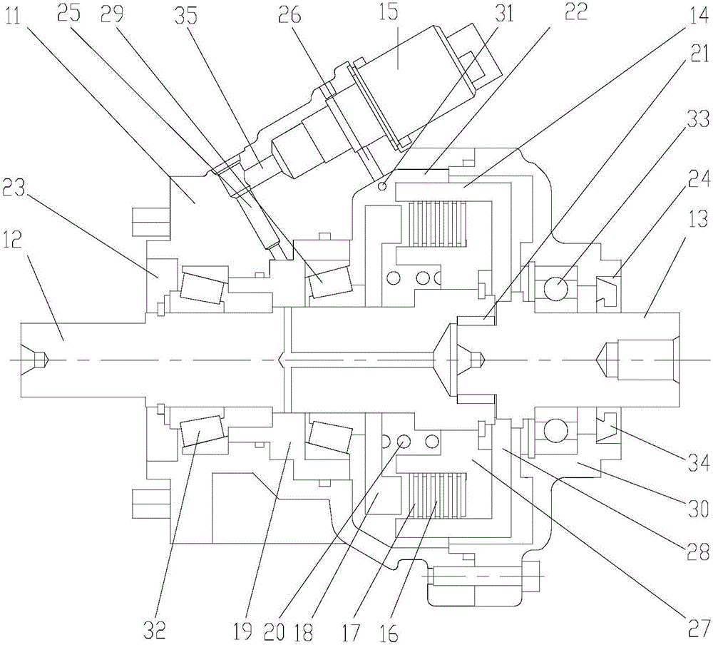
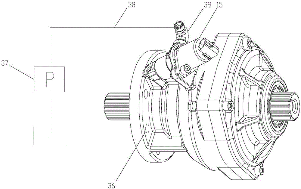
[0026] like figure 1 and 2 As shown, the present invention discloses a power take-off device, which includes a housing 11 , an input shaft 12 , an output shaft 13 , a clutch 14 , a solenoid valve 15 and a bearing cover 30 . The oil pump 37 provides a source of hydraulic oil, and the generated high-pressure oil provides control pressure for the combination and separation of the power take-off device, and at the same time provides oil for lubrication and cooling for the power take-off device. The oil pump 37 is generally installed on the transmission and driven by a power source such as an engine.

[0027] The housing has an inner surface and an outer surface. The inner surface forms a cavity 22, and a first opening 23 and a third opening 35 are formed between the inner and outer surfaces. The first opening 23 and the cavity 22 provide parts to be placed in the housing. Three...


PUM


Abstract

The invention provides a torque extraction device which comprises a shell. A cavity is formed in the inner surface of the shell. An input shaft and an output shaft are coaxially arranged in the cavity of the shell. The portion, extending out of the shell, of the input shaft is connected with a power source. The portion, extending out of the shell, of the output shaft is connected with an output auxiliary device. The input shaft and the output shaft are combined and separated through engagement and disengagement of a clutch. An electromagnetic valve is powered on, a piston is pushed by pressure oil to press the clutch, and the clutch is engaged; the electromagnetic valve is powered off, pressure of the pressure oil disappears, and under the effect of a spring, the clutch is disengaged. When the clutch is engaged, the torque and the power from the power source are transmitted to the output shaft through the input shaft and the clutch, the connected auxiliary device is driven, and therefore the basic functions of the torque extraction device are achieved. The input shaft and the output shaft can be combined and separated without the requirement for stopping rotation of the input shaft or an output device. Meanwhile, a hydraulic oil source brought by an automatic transmission can be conveniently used for control, lubrication and cooling.

Description

【Technical field】 [0001] The invention relates to a transmission auxiliary device, in particular to a power take-off device. 【Background technique】 [0002] Power take-offs are typically used with a power source such as an automotive engine, electric motor or transmission to provide drive power to auxiliary devices. For example, power take-offs are used on on- and off-highway vehicles to provide power to auxiliary devices such as oil pumps, water pumps, motors, compressors, articulating discs, fans, etc. Provide power to oil pumps and various accessories on industrial equipment. Provide power to lawn mowers and hoists on agricultural vehicles. Provide power to oil pumps, propulsion devices, etc. on marine vehicles. [0003] A typical power take-off device consists of a casing, an input gear extending outside the casing, and an output shaft extending outside the casing. When the power take-off device is installed on a rotating power source, its input gear meshes with the ...

Claims


Application Information

Patent Timeline
Patent Type & Authority Applications(China)
IPC IPC(8): F16D25/0638F16D25/08
Inventor 王军王亚锋赵会强马万灵毕乾坤李军高佩王乐顾俊宏
Owner 西安双特智能传动有限公司
Why Eureka
Try Eureka