A large-scale composite structure static indentation damage prefabricated portable testing machine
A composite material and static indentation technology, which is applied in the direction of applying stable tension/pressure to test the strength of materials, can solve problems such as difficult bench-top testing machines, component deformation testing machine travel cannot be satisfied, and difficult to place bench-top testing machines, etc., to achieve The effect of large available stroke
- Summary
- Abstract
- Description
- Claims
- Application Information
AI Technical Summary
Problems solved by technology
Method used
Image
Examples
Embodiment 1
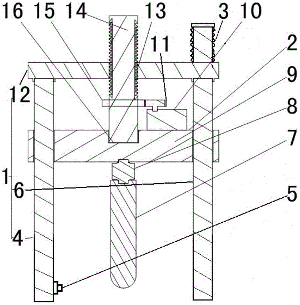
[0033] Such as figure 1 As shown, a composite material structure static indentation damage prefabrication test machine includes a portable support assembly 1, an indenter 7, an indenter feed assembly 2 and a measurement and control assembly, and the indenter feed assembly 2 and the portable support assembly 1 connected, and connected with the indenter 7 in transmission, the measurement and control assembly is connected with the indenter feeding assembly 2, and the indenter can be positioned at multiple positions of the large test piece. The portable support assembly 1 includes a fixed column 4 , a movable column 6 and an upper beam 12 , and the fixed column 4 and the movable column 6 are connected to the upper beam 12 . The upper end of the movable column 6 is a bolt structure, named column bolt 3, the column bolt 3 passes through the upper beam 12, and the movable column 6 can be adjusted to extend out of the upper beam by adjusting the column bolt 3 12 in length.
[0034] ...
Embodiment 2
[0039] Compared with Example 1, the difference is that, as Figure 4 : the lower end of the column 20 is connected to a base 17, four foot bolts 18 are arranged on the base 17, and the length of the foot bolts 18 stretching out from the base 17 can be adjusted independently, so as to be suitable for uneven test pieces On the surface, the base 17 is provided with a hole corresponding to the position of the indenter 7, allowing the indenter 7 to pass through, and the displacement sensor 5 is arranged on the base 17 for measuring the surface of the test piece relative to the The displacement of the base 17.
Embodiment 3
[0041] Compared with Embodiment 1, the difference lies in that the lower end of the column is wound with an electrified electromagnetic coil (without accompanying drawings), and when the electromagnetic coil is electrified, the lower end of the column can be attracted and fixed on the magnetic material. on the test piece.
PUM
 Abstract
Description
Claims
Application Information
 - R&D
- Intellectual Property
- Life Sciences
- Materials
- Tech Scout
- Unparalleled Data Quality
- Higher Quality Content
- 60% Fewer Hallucinations
Browse by: Latest US Patents, China's latest patents, Technical Efficacy Thesaurus, Application Domain, Technology Topic, Popular Technical Reports.
© 2025 PatSnap. All rights reserved.Legal|Privacy policy|Modern Slavery Act Transparency Statement|Sitemap|About US| Contact US: help@patsnap.com


