Method for beam forming and beam pattern optimization based on L-shaped array antenna

An array antenna and optimization method technology, applied to antennas, antenna arrays, instruments, etc., can solve the problem of low angle measurement resolution and angle measurement accuracy of beam patterns, and achieve the effect of optimization of angle measurement resolution and angle measurement accuracy

Active Publication Date: 2015-10-21
HARBIN INST OF TECH
View PDF5 Cites 30 Cited by
  • Summary
  • Abstract
  • Description
  • Claims
  • Application Information

AI Technical Summary

Problems solved by technology

[0003] The purpose of the present invention is to solve the problem that the angle measurement resolution and angle measurement accuracy of the traditional L-shaped array are not high due to the small number of array elements.

Method used


Image

  • Method for beam forming and beam pattern optimization based on L-shaped array antenna
  • Method for beam forming and beam pattern optimization based on L-shaped array antenna
  • Method for beam forming and beam pattern optimization based on L-shaped array antenna

Examples


specific Embodiment approach 1

[0020] Specific embodiment one, a beamforming and beam pattern optimization method based on an L-shaped array antenna, comprising the following steps:

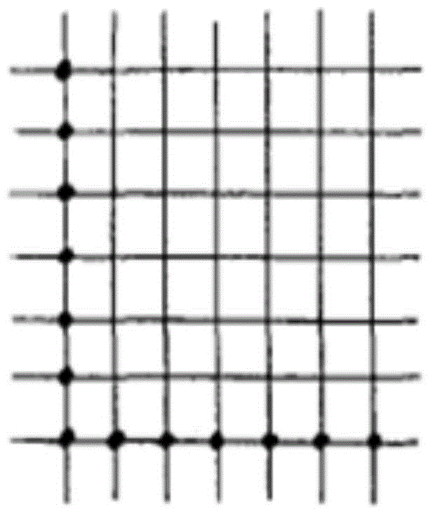
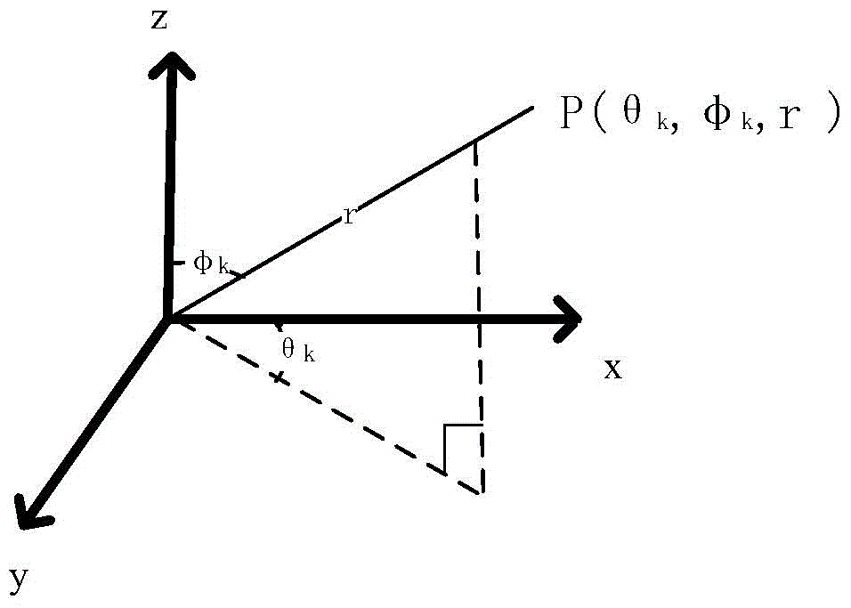
[0021] Step 1: The basic structure of the array obtained by removing the central part of the rectangular array and only retaining two array elements adjacent to the border is an L-shaped array, such as figure 1 As shown; establish a space Cartesian coordinate system xyz, assume that the antenna array exists in the plane formed by the xy axis, and the two array elements of the L-shaped array coincide with the x axis and the y axis respectively, and the space coordinate is P(θ k ,φ k , r) The included angles between an incident beam and the y and z axes are θ k , φ k ; θ k Named the pitch angle of the incident signal, φ k Named as the azimuth of the incident signal, r is the distance from the target to the origin, such as figure 2 shown;

[0022] Step 2: use the two-dimensional spatial beamforming method to establish the ...

specific Embodiment approach 2

[0031] Specific embodiment two, the calculation steps of the maximum caliber Da of the array in step 3 described in this embodiment are as follows:

[0032] For the L-shaped array of the J_K array, use the formula (2) to calculate the maximum array diameter of the x-axis and y-axis of the array respectively:

[0033] Da = N ( N - 1 ) 2 - N R - - - ( 2 )

[0034] In the formula: N=J or K, indicating the number of array elements on the x-axis or y-axis; N R Indicates the number of redundancy.

[0035] N R By looking up Table 1 to get

[0036] Table 1 N and N R Chart

[0037]

[0038] Other steps and parameters are the same as in the first embodiment.

specific Embodiment approach 3

[0039] Specific implementation mode three: the specific implementation steps for encoding and adjusting the array structure of the L-shaped array in step 3 described in this implementation mode are as follows:

[0040] Step 3.1: Encode against L-shaped array of J_K arrays:

[0041] Consider the L-shaped array as a chromosome. For the J_K array, when forming an individual's gene, the J_K array is represented by a binary string randomly generated by the J+K group. The number of bits in the binary number string is Na, and each binary The character string is called a gene on the chromosome; the meaning represented by each binary character string is the distance between the array element and the previous array element, and the above method is used to generate J+K genes, which are stored as the initial population of the genetic algorithm , use the genetic algorithm to perform genetic operations on the initial population;

[0042] Step 3.2: When performing genetic operations, adjust...


PUM


Abstract

Provided is a method for beam forming and beam pattern optimization based on an L-shaped array antenna, and the invention relates to the fields of beam forming and beam pattern optimization of an antenna. According to the invention, in order to solve the problems of low beam pattern angle measurement resolution and angle measurement accuracy resulting from less array elements in the traditional L-shaped array, the method comprises steps of: firstly, establishing a beam pattern F of an antenna for the L-shaped array by using a beam forming method in two-dimensional space, encoding an array structure of the L-shaped array, then adjusting the codes and building a fitness function, and with the beam pattern performance as an optimization target, organizing and optimizing the L-shaped array with a genetic algorithm to obtain an optimized non-uniform L-shaped array element arrangement; on the basis of the array element arrangement, further establishing a fitness function, and by using the genetic algorithm, calculating an optimal weight w for each array element of the L-shaped array; and introducing the optimized non-uniform L-shaped array element arrangement and the weight w into the beam pattern F to implement beam pattern optimization. The present invention is applicable to beam forming and beam pattern optimization of the L-shaped array antenna.

Description

technical field [0001] The present invention relates to antenna beamforming and a method for beam pattern optimization. Background technique [0002] In recent years, the technology of using linear array to measure angle information has been developed rapidly. However, linear array angle measurement has its limitation, that is, only one-dimensional angle information can be obtained. For the two-dimensional angular information of the signal, it must be measured with an area array. According to the research of Hua Yingbo et al. in 1991, for the measurement of two-dimensional angles, the L-shaped array has higher potential angle measurement accuracy than other simple two-dimensional arrays (such as circular arrays, cross arrays, etc.). At the same time, because the L-shaped array also has the advantages of simple structure and easy array arrangement, it has become a research hotspot. However, there is a serious problem with the L-shaped array. Compared with the uniform rectan...

Claims


Application Information

Patent Timeline
Patent Type & Authority Applications(China)
IPC IPC(8): G06F17/50H01Q21/00
Inventor 位寅生陈文驰
Owner HARBIN INST OF TECH
Why Eureka
Try Eureka