
Display panel and manufacturing method thereof, and TFT test method

A technology for display panels and manufacturing methods, which is applied in semiconductor/solid-state device manufacturing, semiconductor/solid-state device testing/measurement, electrical measurement, etc., and can solve problems such as the inability to comprehensively measure the display effect of electroluminescent layers and the electrical characteristics of thin-film transistors

Active Publication Date: 2015-10-21
BOE TECH GRP CO LTD
View PDF4 Cites 22 Cited by
  • Summary
  • Abstract
  • Description
  • Claims
  • Application Information

AI Technical Summary

Problems solved by technology

[0004] In summary, the disadvantages in the prior art are that the display effect of the electroluminescent layer and the electrical characteristics of the thin film transistor cannot be comprehensively measured.

Method used


Image

  • Display panel and manufacturing method thereof, and TFT test method
  • Display panel and manufacturing method thereof, and TFT test method
  • Display panel and manufacturing method thereof, and TFT test method

Examples


Embodiment 1

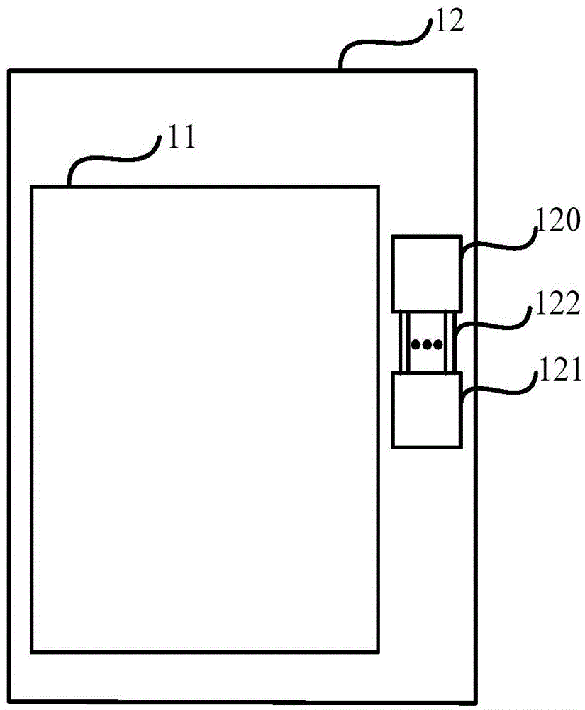
[0043] See figure 1 A display panel provided by an embodiment of the present invention includes a display area 11 and a peripheral area 12 outside the display area. The peripheral area 12 includes: an electroluminescent layer test area 120, a TFT test area 121, and a lead line 122; among them,

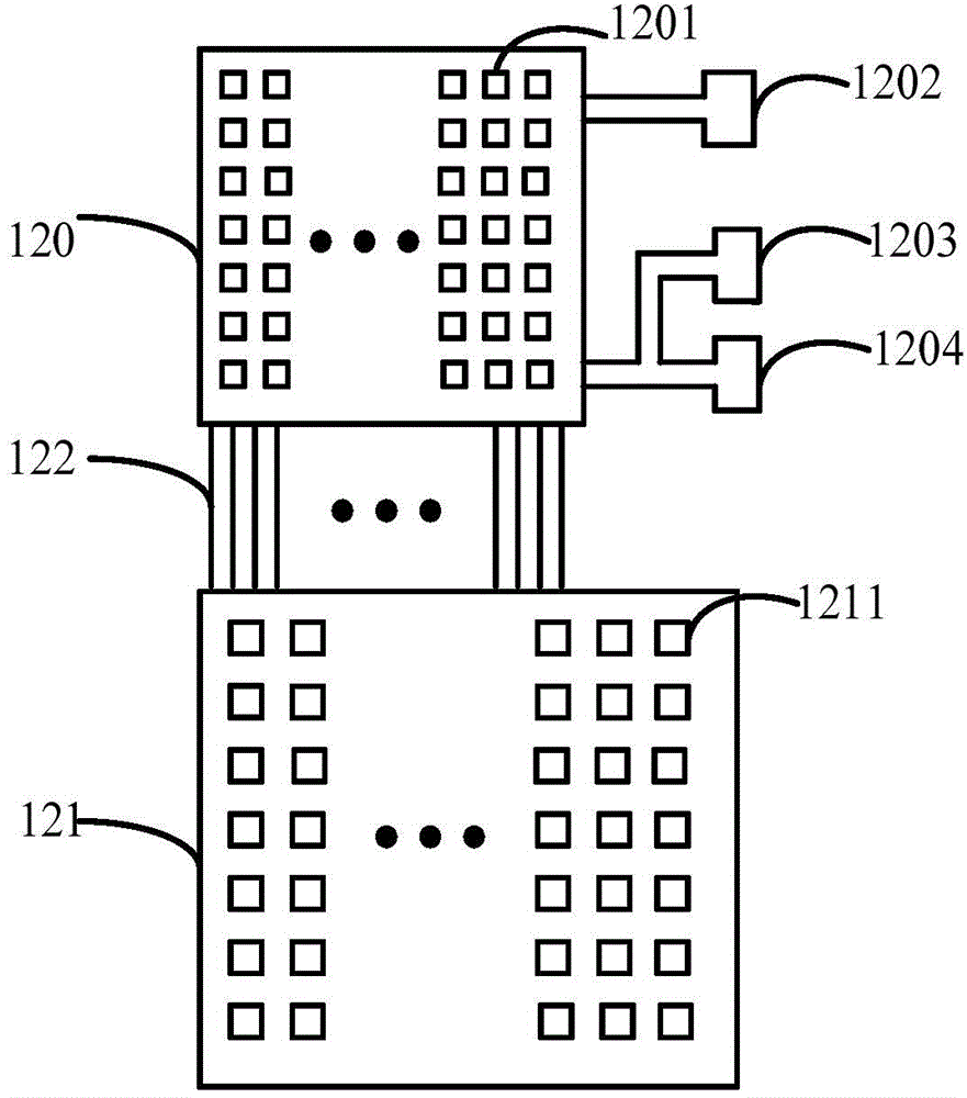
[0044] See figure 2 The specific structure of the electroluminescent layer test area 120, the TFT test area 121, and the lead line 122 in the peripheral area provided by the embodiment of the present invention. The electroluminescence layer test area 120 includes a plurality of thin film transistors 1201 having electroluminescence layers, a first test line 1202 connecting the sources of the plurality of thin film transistors having electroluminescence layers, and connecting a plurality of thin film transistors having electroluminescence layers. The switch lead 1203 and the second test line 1204 of the gate of the thin film transistor of the layer;

[0045] The TFT test area 121 includes a...


PUM


Abstract

The invention provides a display panel and a manufacturing method thereof, and a TFT test method in order to comprehensively evaluate the display effect of electroluminescent layers and the electrical characteristics (such as short-range uniformity) of thin-film transistors in a display panel. The display panel comprises a display area and a peripheral area of the display area. The peripheral area comprises an electroluminescent layer test area, a TFT test area, and outgoing lines. The electroluminescent layer test area includes multiple thin-film transistors respectively provided with an electroluminescent layer, a first test line connected with the sources of the multiple thin-film transistors respectively provided with an electroluminescent layer, and a switch lead and a second test line which are connected with the gates of the multiple thin-film transistors respectively provided with an electroluminescent layer. The TFT test area includes multiple thin-film transistors. Each of the multiple outgoing lines is used to connect the source and drain metal layer of one thin-film transistor in the electroluminescent layer test area and the source and drain metal layer of one thin-film transistor in the TFT test area.

Description

Technical field [0001] The invention relates to the field of liquid crystal panel display, in particular to a display panel, a manufacturing method thereof, and a TFT testing method. Background technique [0002] With the gradual improvement of people’s living standards, people’s requirements for display quality are getting higher and higher. In the prior art, the technology of liquid crystal displays (LCD) has been very mature, and the application of liquid crystal displays is also very extensive, such as mobile phones, cameras, Computers, TVs and other display screens are all liquid crystal displays. With the massive demand for products, the development of display technology has been objectively promoted, and new display technologies have emerged, such as low-temperature polysilicon (LTPS) and organic diode (OLED) display technologies. Among them, the active matrix organic light-emitting diode panel (AMOLED) is the key development target of the next-generation display technolo...

Claims


Application Information

Patent Timeline
IPC IPC(8): H01L27/32H01L23/544H01L21/77H01L21/66
CPCG09G3/006G09G3/3208H01L22/34G09G2300/0417H01L27/1214G02F1/136254G02F1/136295H10K59/1213H10K59/1201G01R31/2825G02F1/1309G02F1/133345G02F1/136286G02F1/1368
Inventor 王祖强李光孙亮陆小勇
Owner BOE TECH GRP CO LTD
Learn More