Mobile terminal and heat radiation structure thereof

A mobile terminal and heat dissipation structure technology, applied in the direction of cooling/ventilation/heating transformation, etc., can solve the problems of heat dissipation efficiency in high temperature areas, complex camera structure design, etc., to ensure work stability and service life, ensure work reliability and The effect of improving the service life and heat dissipation efficiency

Active Publication Date: 2015-10-21
GUANGDONG OPPO MOBILE TELECOMM CORP LTD
View PDF4 Cites 17 Cited by
  • Summary
  • Abstract
  • Description
  • Claims
  • Application Information

AI Technical Summary

Problems solved by technology

[0004] At present, the camera part is usually wrapped with a layer of copper foil or a layer of graphite is pasted on the back to solve the heat dissipation problem. However, with the compression of the structural space and the limitation of the thickness of the whole machine, the structural design of the camera part is becoming more and more complicated.
For example, in order to solve the problem of the thickness of the whole machine, the motherboard module will be placed in the middle frame. At this time, due to the thickness of the camera, the metal area on the back of the camera is at the same height as the motherboard module. Graphite or copper foil to solve the heat dissipation problem
[0005] In addition, since the camera part is generally located in the area close to the main board module, and the main board module area and the camera part are both high-temperature areas, even if the camera part is effectively connected to the middle frame, there will also be the disadvantage that the high-temperature area will affect the heat dissipation efficiency.

Method used


Image

  • Mobile terminal and heat radiation structure thereof
  • Mobile terminal and heat radiation structure thereof
  • Mobile terminal and heat radiation structure thereof

Examples


Embodiment Construction

[0024] The technical solutions of the present invention will be further described below in conjunction with the accompanying drawings and through specific implementation methods.

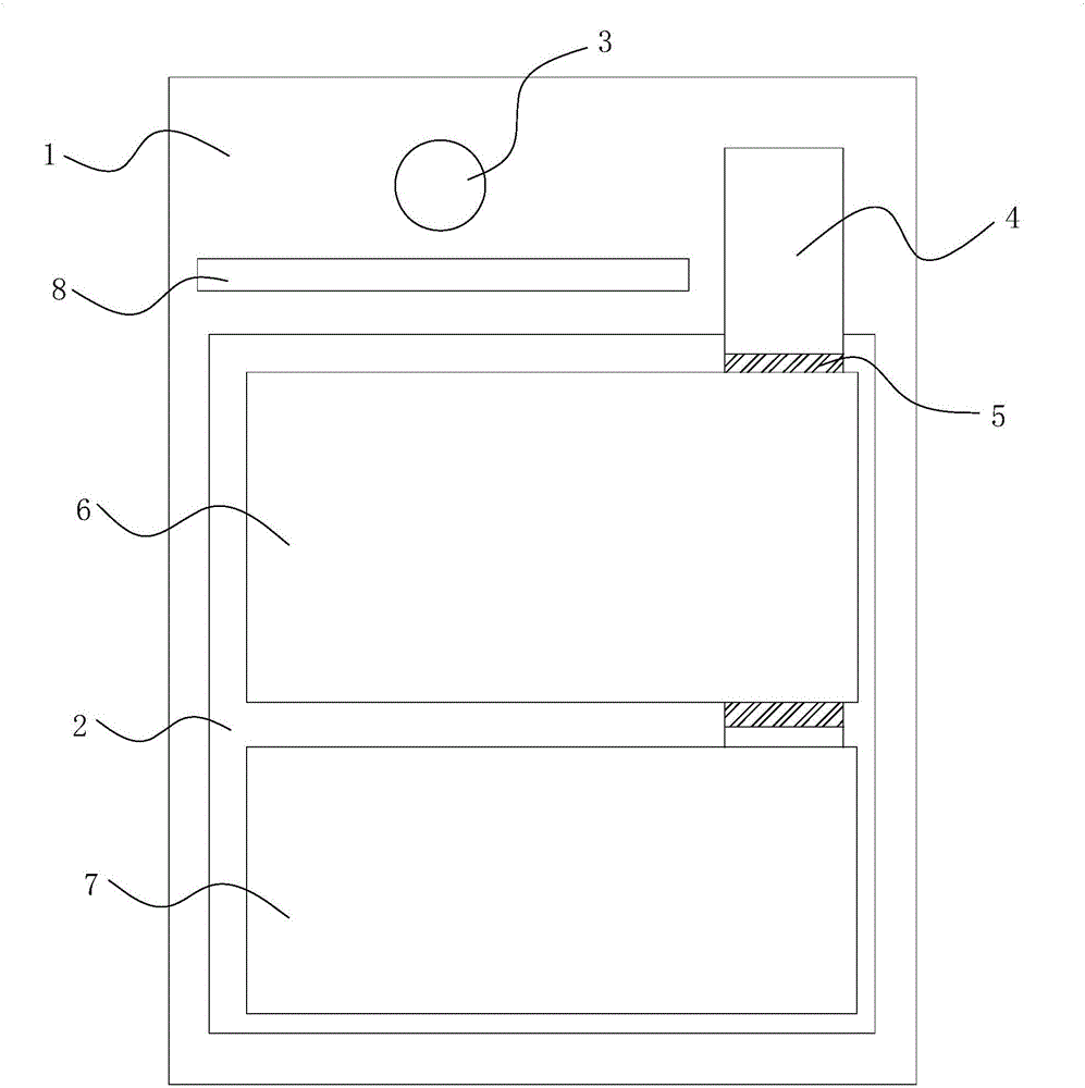
[0025] Such as Figure 1~4 As shown, in this embodiment, a heat dissipation structure of a mobile terminal includes a mounting bracket, and a mainboard heat dissipation area for controlling the temperature rise of the mainboard module and a mainboard heat dissipation area for controlling the temperature rise of the mainboard module and the camera module 3 are arranged side by side on the mounting bracket. The camera heat dissipation area for temperature rise, the main board heat dissipation area is arranged close to one side of the main board module, and the camera heat dissipation area is located on the side of the main board heat dissipation area away from the camera module 3 .

[0026] In this embodiment, the camera module 3 is dissipated by setting a special camera heat dissipation area, so as t...


PUM


Abstract

The invention discloses a heat radiation structure of a mobile terminal. The heat radiation structure comprises an installation bracket, wherein a mainboard heat radiation region and a camera shooting heat radiation region are arranged on the installation bracket in parallel, the mainboard heat radiation region is used for controlling temperature rise of a mainboard module, the camera shooting heat radiation region is used for controlling temperature rise of a camera module, the mainboard heat radiation region adjoins to one side of the mainboard module, the camera shooting heat radiation region is arranged on one side, away from the camera module, of the mainboard heat radiation region. According to the mobile terminal and the heat radiation structure thereof, the camera shooting heat radiation region used for controlling temperature rise of the camera module is arranged in a region outside the mainboard module and the camera module, so that the heat of the camera module is isolated from that of the mainboard module, and the heat of the mainboard module and the camera module is prevented from interactively affecting the heat radiation efficiency of the two modules even normal operation of the two modules, thereby ensuring heat radiation efficiency and stable operation of the mainboard module and the camera module simultaneously.

Description

technical field [0001] The present invention relates to the technical field of terminal heat dissipation, in particular to a heat dissipation structure of a mobile terminal and the mobile terminal, and further, to a heat dissipation structure of a mobile phone and the mobile phone. Background technique [0002] In modern society, the pace of life of people is getting faster and faster, and the communication between people is getting closer and more frequent. People rely heavily on communication equipment. Among them, the mobile phone is one of the most widely used communication terminals. The mobile phone is favored and popularized by people because of its portability, simple operation and comprehensive functions. The mobile phone is a mobile terminal with a small size, but people have a high demand for the functions and processing capabilities of the mobile phone. Therefore, the integration of mobile phones is getting higher and higher, and the CPU cores of mobile phones ar...

Claims


Application Information

Patent Timeline
Patent Type & Authority Applications(China)
IPC IPC(8): H05K7/20
Inventor 李路路
Owner GUANGDONG OPPO MOBILE TELECOMM CORP LTD
Why Eureka
Try Eureka