Inertia sensor

A technology of inertial sensors and sensor elements, which is applied in the field of inertial sensors and can solve the problems of S/N deterioration of sensor output characteristics

Active Publication Date: 2015-10-21
PANASONIC INTELLECTUAL PROPERTY MANAGEMENT CO LTD
View PDF6 Cites 5 Cited by
  • Summary
  • Abstract
  • Description
  • Claims
  • Application Information

AI Technical Summary

Problems solved by technology

[0007] In order to amplify the output from the inertial sensor 1 having a switching configuration using the switching eleme

Method used


Image

  • Inertia sensor
  • Inertia sensor
  • Inertia sensor

Examples


Embodiment approach 1

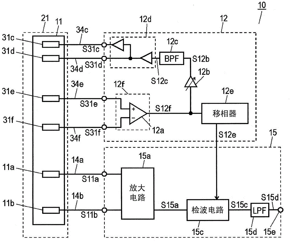
[0053] figure 1 It is a structural diagram of the inertial sensor 10 in Embodiment 1 of this invention. Inertial sensor 10 in Embodiment 1 is an angular velocity sensor that detects angular velocity as an inertial force. The inertial sensor 10 includes: a sensor element 21 ; a drive circuit 12 for driving the sensor element 21 ; and a detection circuit 15 for detecting an angular velocity applied to the sensor element 21 .

[0054] The sensor element 21 has: the vibrator 11; detection units 11a, 11b; drive units 31c, 31d; and monitoring units 31e, 31f. The detection units 11 a and 11 b , the driving units 31 c and 31 d , and the monitoring units 31 e and 31 f are provided on the vibrator 11 . Driving signals S31c, S31d for driving and vibrating the vibrator 11 are respectively input from the driving circuit 12 to the driving parts 31c, 31d. The monitoring units 31 e and 31 f output the monitoring signals S31 e and S31 f generated based on the driving vibration of the vibra...

Embodiment approach 2

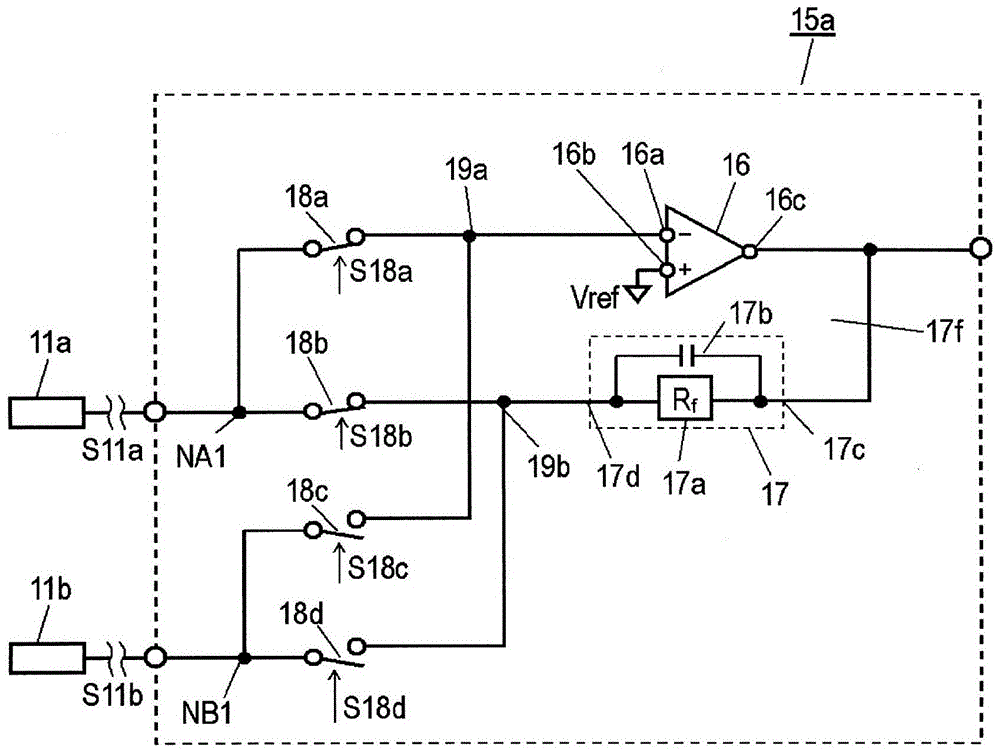
[0134] Figure 12 It is a circuit block diagram of the amplifier circuit 100 of the inertial sensor in Embodiment 2. exist Figure 12 In pair with figure 2 The same parts of the amplifier circuit 15a in the illustrated first embodiment are denoted by the same reference numerals. Figure 12 The shown sensor element 21 also has a detection portion 11 c provided on the vibrator 11 . Figure 12 The amplification circuit 100 in Embodiment 2 shown in figure 2 The amplifier circuit 15a in Embodiment 1 shown further includes a switching element 18e provided between the detection unit 11c and the input terminal 16a of the amplifier 16, and a switch provided between the detection unit 11c and the terminal 17d of the feedback circuit unit 17. Element 18f. The detection unit 11a is connected to the switching elements 18a and 18b at a node NA1. The detection unit 11b is connected to the switching elements 18c and 18d at the node NB1. The detection unit 11c is connected to the swit...

Embodiment approach 3

[0187] Figure 23 It is a configuration diagram of inertial sensor 110 in Embodiment 3 of the present invention. exist Figure 23 in, right with figure 1 The same parts of the inertial sensor 10 in Embodiment 1 shown are denoted by the same reference numerals. Figure 23 The inertial sensor 110 shown replaces the figure 1 The sensor element 21 and the amplifier circuit 15 a of the inertial sensor 10 shown include the sensor element 121 and the amplifier circuit 400 . Similar to the inertial sensor 10 in the first embodiment, in the inertial sensor 110 in the third embodiment, the detection circuit 15c performs synchronous detection on the detection signal output from the amplifier circuit 400 to output a detection signal S15c.

[0188] The sensor element 121 is in figure 1 The shown sensor element 21 further includes detection units 11am and 11bm provided on the vibrator 11 . The detection parts 11a and 11am are arranged at positions symmetrical to each other with res...


PUM


Abstract

This inertia sensor is provided with: a first and a second detection unit for respectively outputting a first and a second detection signal; an amplifier having input terminals for selectively inputting the first and second detection signals; a feedback circuit unit configured to be connected in parallel to the amplifier input terminals and output terminal; a first switch element situated between the first detection unit and an input terminal of the amplifier; a second switch element situated between the first detection unit and the feedback circuit unit; a third switch element situated between the first detection unit and an input terminal of the amplifier; and a fourth switch element situated between the second detection unit and the feedback circuit unit. According to this inertia sensor, the output characteristics of the feedback circuit unit are stabilized, and the occurrence of unwanted signals is minimized.

Description

technical field [0001] The present invention relates to inertial sensors used in automobiles, airplanes, ships, robots, and other various electronic devices. Background technique [0002] Figure 36A is a block diagram of a conventional inertial sensor 1 . The inertial sensor 1 has: three piezoelectric elements 2 for detecting inertial force; a switching element 3 using a field effect transistor; and an amplifier circuit 4 using an operational amplifier. In the inertial sensor 1, in order to detect the inertial forces in the three directions orthogonal to each other, the switching element 3 provided between the piezoelectric element 2 and the amplifier circuit 4 is switched, so that the three piezoelectric elements 2 The output is fetched as 1 output. In this way, by using the switching element 3 to sequentially switch and extract outputs from the plurality of piezoelectric elements 2 , a detection circuit capable of multi-axis detection can be constituted by one amplifier...

Claims


Application Information

Patent Timeline
IPC IPC(8): G01C19/5614H01L41/113H03F1/26
CPCG01C19/5776H01L41/1132H10N30/302G01P15/0802G01P15/097G01P15/0888
Inventor 佐佐木刚
Owner PANASONIC INTELLECTUAL PROPERTY MANAGEMENT CO LTD
Why Eureka
Try Eureka