Magnetic sensor and magnetic balance type current sensor utilizing same

a magnetic sensor and current sensor technology, applied in the field of magnetic sensors and magnetic balance type current sensors utilizing magnetic sensors, can solve the problems of difficult to obtain a sufficiently stable output characteristic, difficult to sufficiently increase antiferromagnetic coupling between pins 1, etc., to suppress the amr effect, increase antiferromagnetic coupling, and stable output characteristic

Active Publication Date: 2015-02-10
ALPS ALPINE CO LTD
View PDF53 Cites 3 Cited by
  • Summary
  • Abstract
  • Description
  • Claims
  • Application Information

AI Technical Summary

Benefits of technology

[0008]In view of the above-mentioned point, the present invention is made and provides a magnetic sensor capable of suppressing the occurrence of an AMR effect due to a fixed resistance element and a magnetic balance type current sensor capable of obtaining a sufficiently stable output characteristic when an ambient temperature has changed.
[0010]According to this configuration, since the antiparallel coupling film of the self-pinned type ferromagnetic fixed layer is the Ru film having the thickness of the first peak of the antiferromagnetic coupling effect and a difference in magnetization amount between the first ferromagnetic film and the second ferromagnetic film is substantially zero, it may be possible to suppress the occurrence of an AMR effect due to a fixed resistance element.
[0014]According to this configuration, since a magnetic sensor suppressing the occurrence of the AMR effect is used, it may be possible to obtain a sufficiently stable output characteristic.

Problems solved by technology

In this case, since the film thickness of the second peak is used for the Ru used for an antiparallel coupling film, it may be difficult to sufficiently increase antiferromagnetic coupling between the Pin1 and the Pin2. Accordingly, it may be easy for the Pin1 and the Pin2 to move owing to an external magnetic field, and it may be easy for an anisotropic magnetoresistance effect (AMR effect) to occur.
It may be ideal that the resistance value of the fixed resistance element remains constant even if the external magnetic field has changed, and if the AMR effect is large, it may be difficult to obtain a sufficiently stable output characteristic.

Method used


Image

  • Magnetic sensor and magnetic balance type current sensor utilizing same
  • Magnetic sensor and magnetic balance type current sensor utilizing same
  • Magnetic sensor and magnetic balance type current sensor utilizing same

Examples


Embodiment Construction

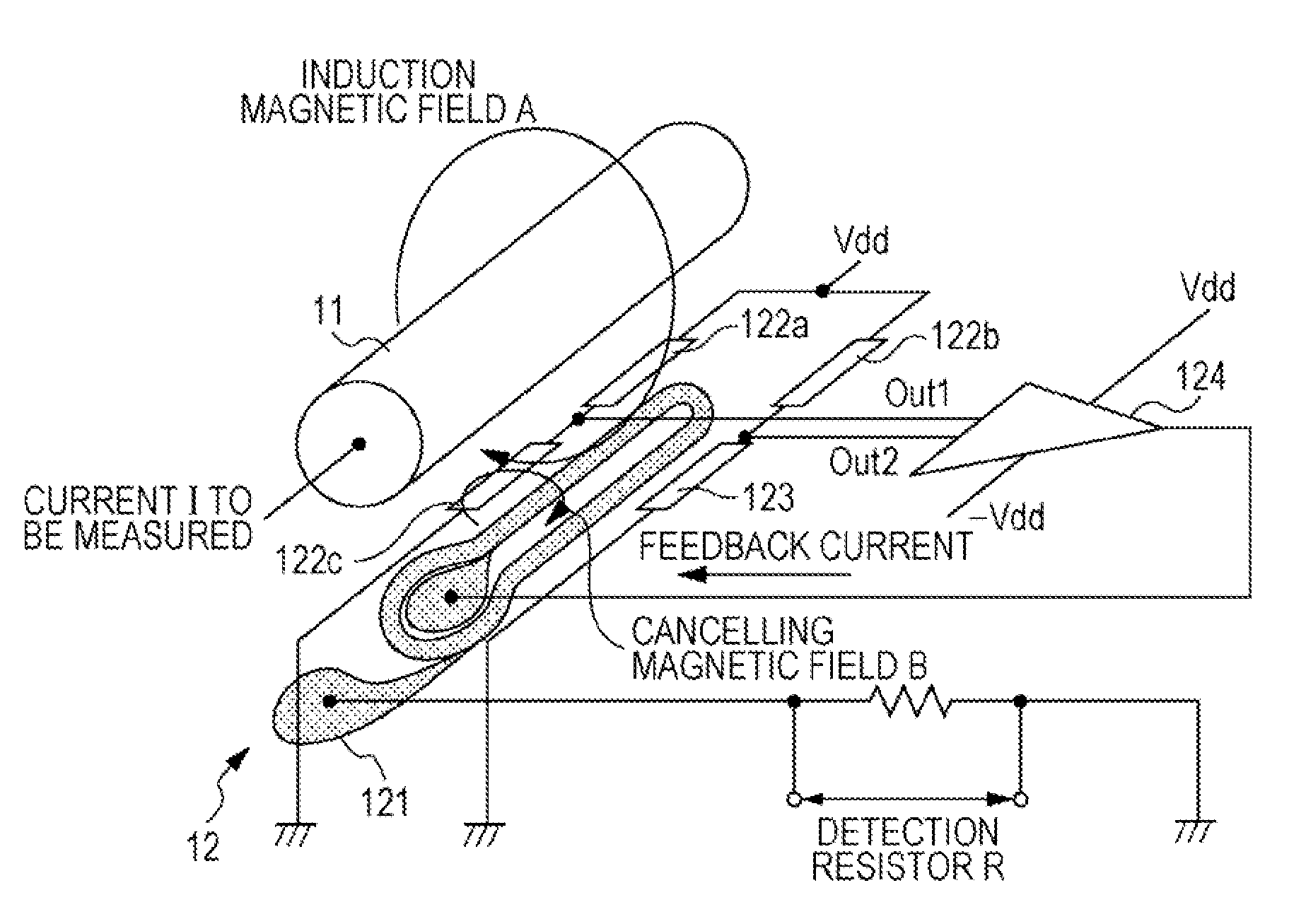
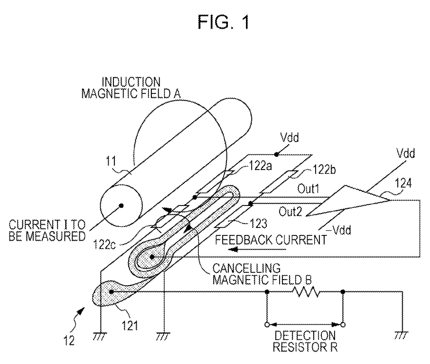
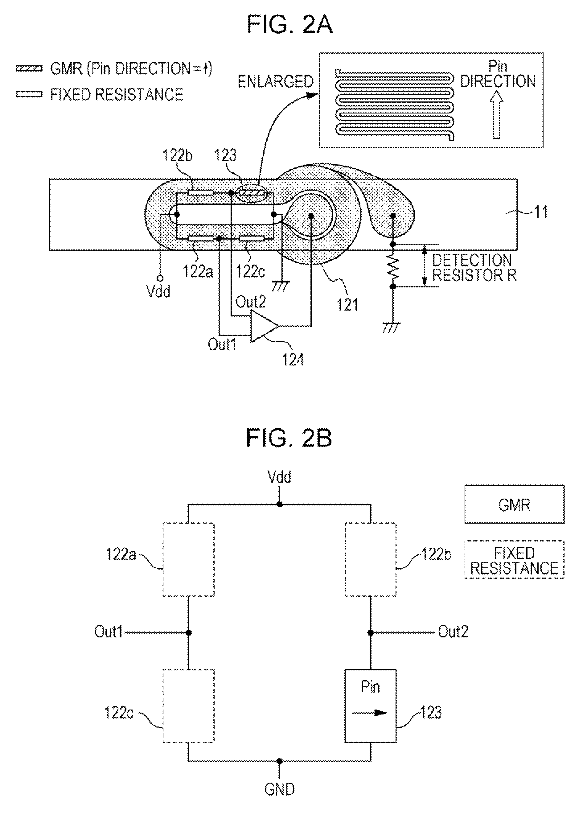
[0034]Hereinafter, embodiments of the present invention will be described in detail with reference to accompanying drawings. FIG. 1 and FIG. 2A are diagrams illustrating a magnetic balance type current sensor according to an embodiment of the present invention. In the present embodiment, the magnetic balance type current sensor illustrated in FIG. 1 and FIG. 2A is installed adjacent to a conductor 11 in which a current Ito be measured flows. The magnetic balance type current sensor includes a feedback circuit 12 for causing a magnetic field (cancelling magnetic field) for cancelling out an induction magnetic field due to the current Ito be measured which flows in the conductor 11. The feedback circuit 12 has a feedback coil 121, wound in a direction for cancelling out a magnetic field generated owing to the current Ito be measured, three fixed resistance elements 122a to 122c, and one magnetoresistance effect element 123.

[0035]The feedback coil 121 is configured using a planar coil....


PUM


Abstract

A magnetism sensor comprises a magnetoresistive element, the resistance of which changes due to the application of an induced magnetic field from the current being measured, and a fixed-resistance element. The fixed-resistance element has a self-pinned ferromagnetic fixed layer comprising a first ferromagnetic film and a second ferromagnetic film coupled antiferromagnetically with an antiparallel coupling film interposed therebetween. The antiparallel coupling film is a ruthenium film that exhibits an antiferromagnetic coupling effect with a first peak thickness. The difference between the degrees of magnetization of the first ferromagnetic film and the second ferromagnetic film is effectively zero.

Description

CLAIM OF PRIORITY[0001]This application is a Continuation of International Application No. PCT / JP2011 / 055185 filed on Mar. 7, 2011, which claims benefit of Japanese Patent Application No. 2010-056156 filed on Mar. 12, 2010. The entire contents of each application noted above are hereby incorporated by reference.BACKGROUND OF THE INVENTION[0002]1. Field of the Invention[0003]The present invention relates to a magnetic sensor and a magnetic balance type current sensor utilizing the magnetic sensor.[0004]2. Description of the Related Art[0005]In an electric vehicle, a motor is driven using electricity generated by an engine, and the intensity of the current for driving the motor is detected by, for example, a current sensor. The current sensor includes a magnetic core disposed around a conductor and having a cutaway portion (core gap) formed at a portion thereof, and a magnetic detecting element disposed within the core gap.[0006]As the magnetic detecting element of the current sensor,...

Claims


Application Information

Patent Timeline
Patent Type & Authority Patents(United States)
IPC IPC(8): G01R33/09B82Y25/00G01R15/20
CPCG01R33/093B82Y25/00G01R15/205
Inventor IDE, YOSUKESAITO, MASAMICHI
Owner ALPS ALPINE CO LTD
Why Eureka
Try Eureka