Foot drying machine, and footwear drying and foot drying combined apparatus

A technology for drying feet and toes, which is used in household cleaning devices, cleaning of boots and shoes, chemistry, etc., can solve the problems of inability to dry the soles of the feet, inconvenience for users to stand and use, and it takes a lot of time to achieve high drying efficiency. Effect

Active Publication Date: 2015-10-28
潘鑫欣
View PDF11 Cites 15 Cited by
  • Summary
  • Abstract
  • Description
  • Claims
  • Application Information

AI Technical Summary

Problems solved by technology

There is the most water on the soles of the feet after taking a bath, but the existing foot drying equipment cannot dry the soles of the feet. It takes a lot of time to dry the soles of the feet, and it is not convenient for users to stand and use

Method used


Image

  • Foot drying machine, and footwear drying and foot drying combined apparatus
  • Foot drying machine, and footwear drying and foot drying combined apparatus
  • Foot drying machine, and footwear drying and foot drying combined apparatus

Examples


Embodiment 1

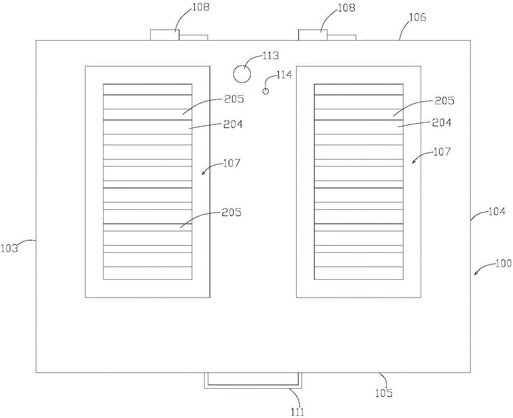
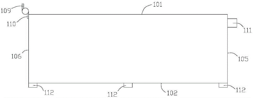
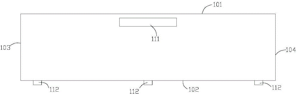
[0101] Example 1, see Figure 1 ~ Figure 4 .

[0102] A foot drying machine in this embodiment includes a housing 100 , and a water collection tank 200 , an air duct 300 , a PTC ceramic heating chip 400 and a fan 500 are arranged in the housing 100 .

[0103] The casing 100 includes a top panel 101 , a bottom panel 102 , a left side panel 103 , a right side panel 104 , a front side panel 105 and a rear side panel 106 . The top board 101 has two foot rest areas 107, and the two foot rest areas are respectively provided with openings. There are two water collection tanks 200, which are respectively arranged directly below the foot rest area 107. The water collecting tank 200 is basin-shaped, and the water collecting tank 200 has an air outlet opening upward. The PTC ceramic heating sheet 400 can heat the air, and the fan 500 can make the air flow, and the combination of the PTC ceramic heating sheet 400 and the fan 500 can generate flowing hot air. The PTC ceramic heating sh...

Embodiment 2

[0113] Example 2, see Figure 5 and Figure 6 .

[0114] This embodiment provides a foot drying machine. Compared with the foot drying machine in Embodiment 1, the deflector 202 and the foot resting plate 204 are eliminated, and a plurality of branch pipes 700 are arranged below the foot resting area 107 . The branch pipe 700 communicates with the air guide pipe 300 through the sump 200 , and the diameter of the branch pipe 700 is smaller than that of the air guide pipe 300 , and the air outlet of the branch pipe 700 faces the foot area 107 . The top board 101 is provided with a plurality of second ventilation holes 115 in the foot rest area 107, and this top board 101 with ventilation holes replaces the foot rest board 204 of the first embodiment. The foot area 107 includes the toe area and the sole area. Since the toe area is not easy to dry, the branch pipes below the toe area are densely distributed, and the user's toe area is mainly dried.

Embodiment 3

[0115] Example 3, see Figure 7 ~ Figure 9 .

[0116] This embodiment provides a foot drying machine. The difference between this embodiment and Embodiment 1 is that the structure of the air distributor is different. The air distributor of this embodiment not only includes a water collection tank 200, but also includes a first air duct 206 and a second air duct 206. Duct 207 . In addition, a third air duct 208 for blowing the instep is also provided. Refer to Example 1 for the parts not mentioned in this example.

[0117] The projection of the foot rest area 107 on the horizontal plane is a rectangle, and of course other shapes similar to a rectangle can also be used. There are two first air ducts 206 , which are respectively arranged on both sides of the width direction of the foot rest area 107 , and the axis line of the first air duct 206 is arranged along the length direction of the foot rest area 107 . The sidewall of the first air duct 206 is provided with a pluralit...


PUM


Abstract

The invention specifically provides a foot drying machine and relates to the field of a household electrical appliance. The foot dying machine comprises a housing, and a wind distributor, water collecting tanks, a guide duct, a heating member and a fan which are arranged in the housing. The top portion of the housing is provided with foot placing areas, and the water collecting tanks are disposed below the foot placing areas; the wind distributor is arranged in the water collecting tanks and is provided with an air outlet oriented towards the foot placing areas; one end of the guide duct is an air inlet end and the other end is an air outlet end, and the air outlet end is connected with the wind distributor; and the heating member and the fan are arranged at the air inlet end of the guide duct. The foot drying machine provided by the invention can generate hot air and dry soles, enables water on feet not to drop to the fan and the heating member, and has no influences on parts inside the housing. A user, after having a bath, can directly stand at the foot placing area for drying. The invention further provides a footwear drying and foot drying combined apparatus. A footwear drying machine and the foot drying machine cooperate for application, and additional consumption of time of the user is unnecessary.

Description

technical field [0001] The invention relates to the field of household appliances, in particular to a foot drying machine and a combination device for drying shoes and feet. Background technique [0002] Most people dry their feet with dry cotton products after bathing, especially in winter. Family members may reuse the same cotton product, and after frequent use of cotton products, cotton products It is easy to breed bacteria, and there are potential risks of cross-infection of athlete's foot and foot odor. Cotton products can absorb moisture from the feet through the principle of adsorption, but they cannot completely dry the feet, especially the roots of the toes. [0003] In modern society, some people have thought of using a foot drying machine to solve the problem of cross-infection, unenvironmental protection and unhygienic living habits. The Chinese patent document with the publication number CN201734628U discloses a foot drying machine, including a shape The housi...

Claims


Application Information

Patent Timeline
Patent Type & Authority Applications(China)
IPC IPC(8): A47K10/48A47L23/20A61L2/20
Inventor 潘鑫欣
Owner 潘鑫欣
Why Eureka
Try Eureka