Round pipe machining clamping device

A technology of clamping device and round tube, applied in auxiliary devices, positioning devices, metal processing and other directions, can solve the problems of poor fixation and poor processing effect, etc.

Inactive Publication Date: 2015-10-28
CHENGDU MATSUKAWA METAL MATERIALS
View PDF4 Cites 11 Cited by
  • Summary
  • Abstract
  • Description
  • Claims
  • Application Information

AI Technical Summary

Problems solved by technology

[0003] When the existing round tube is processed, it is often due to p

Method used


Image

  • Round pipe machining clamping device

Examples


Example Embodiment

[0009] The present invention will be further described in detail below through specific implementation examples in conjunction with the accompanying drawings.

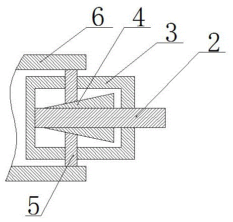
[0010] figure 1 The clamping device for round tube processing provided by the present invention is shown, including a pull rod 2, a roller 3, a square block 4 and a slider 5. The inside of the drum 3 is a cavity, and the cylindrical surface of the drum 3 is provided with four through holes, the four through holes are evenly distributed, and the plane formed by the center lines of the four through holes is perpendicular to the axis of the drum 3; A tie rod 2 is provided. The tie rod 2 is provided with a square block 4. The plane parallel to the axis of the square block 4 and the drum 3 is an inclined plane. Each inclined plane is provided with a sliding block 5 matching the inclined plane. The sliding block 5 and the corresponding through hole Fit and pass through the through hole.

[0011] By pushing the pull rod 2 into t...


PUM


Abstract

The invention discloses a round pipe machining clamping device. The round pipe machining clamping device is characterized in that the clamping device comprises a roller, a cavity is formed inside the roller, four through holes are formed in the outer circle face of the roller and evenly distributed, and a plane formed by the center lines of the four through holes is perpendicular to the axis of the roller; a pull rod is arranged in the roller, and a square block is arranged on the pull rod; planes, parallel to the axis of the roller, of the square block are inclined faces, the inclined faces are provided with sliding blocks matched with the inclined faces, and the sliding blocks are matched with the corresponding through holes and penetrate through the through holes. According to the clamping device, the work efficiency is improved, and cost is reduced.

Description

Technical field [0001] The invention relates to the field of round tube processing equipment, in particular to a round tube processing clamping device. Background technique [0002] In the prior art, round pipes are often processed in various ways, such as welding flanges, drilling or cutting, etc. Therefore, it is often necessary to fix the round pipes. However, the round pipes are different from common-shaped workpieces and are difficult to fix and process. For example, when welding a flange, the connection between the flange and the round pipe is not strong. It is usually necessary to lay the flange flat on the workbench, and then place the round pipe on the flange body to enhance the welding. Time stability. [0003] When the existing round tube is processed, it is often due to poor fixation, resulting in poor processing effects and other shortcomings. Summary of the invention [0004] The purpose of the present invention is to provide a round tube processing clamping device t...

Claims


Application Information

Patent Timeline
IPC IPC(8): B23K37/053B23Q3/06
CPCB23K37/0531B23K2101/06B23Q3/064
Inventor 周建川
Owner CHENGDU MATSUKAWA METAL MATERIALS
Why Eureka
Try Eureka