Novel gas-liquid pressure cylinder

A pressurized cylinder and hydraulic cylinder technology, applied in the field of new gas-liquid pressurized cylinders, can solve the problems of easy oil leakage, shortened service life of pressurized cylinders, slow return, etc., achieve fast and stable preloading, increase work The effect of high efficiency and fast return speed

Active Publication Date: 2015-10-28
湖北奥科视听工程有限公司
View PDF6 Cites 13 Cited by
  • Summary
  • Abstract
  • Description
  • Claims
  • Application Information

AI Technical Summary

Problems solved by technology

[0002] The air-liquid booster cylinder is widely used in stamping equipment and other occasions that require a large thrust. The working process of the air-liquid booster cylinder is generally preloading, boosting and return. The gas-liquid pressurized cylinder generally has the following problems: 1) the return stroke is driven by liquid, and the return stroke is slow; 2) the liquid is pre-pressed by gas, the pre-pressing process is cumbersome and the efficiency is low; 3) the reset of the booster piston is complicated
[0003] At the same time, due to the urgent need to improve the working efficiency of the pressurized cylinder, the factory blindly increases the pressure of the working air source, which will cause the sealing ring in the cylinder to bear an excessive load, and it is very easy to cause oil leakage after long-term work, and the working piston rod is weak and other failures. problems, greatly shortening the service life of the entire pressurized cylinder, and burying safety hazards for normal production

Method used


Image

  • Novel gas-liquid pressure cylinder
  • Novel gas-liquid pressure cylinder
  • Novel gas-liquid pressure cylinder

Examples


Embodiment Construction

[0023] The present invention will be further described below in conjunction with the accompanying drawings and embodiments.

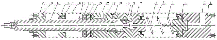
[0024] Such as figure 1 As shown, a new type of gas-liquid booster cylinder includes a front end cover 19, a working cylinder body 16, a hydraulic cylinder body 10, a gas-liquid cylinder conversion middle cover 8, a cylinder body 5 and a rear end that are sealed in sequence. Cover 1, the two ends of the working cylinder block 16, the hydraulic cylinder block 10, the gas-liquid cylinder conversion middle cover 8 and the cylinder block 5 are all open, and the rear end cover 1 is provided with the cylinder block 5 Connected pressurized air intake channel 2, cylinder block 5 is provided with a booster piston 3 and a gas-liquid seal block 7, the booster piston 3 is limited by the side wall of the rear end cover 1, and the gas-liquid seal block 7 is passed through the gas-liquid seal block 7. The side wall of the liquid cylinder conversion center cover 8 is ...


PUM


Abstract

The invention relates to a novel gas-liquid pressure cylinder. The novel gas-liquid pressure cylinder comprises a front end cover, a working cylinder body, a hydraulic cylinder body, a middle gas-liquid cylinder conversion cover, an air cylinder body and a rear end cover which are all sequentially connected. The rear end cover is provided with a pressurizing air inflow channel. A pressurizing piston and a gas-liquid sealing block are arranged in the air cylinder body. The pressurizing piston is provided with a pressurizing rod. The pressurizing rod penetrates the gas-liquid sealing block in a sealed manner and is sleeved with a reset spring with the two ends making contact with the pressurizing piston and the gas-liquid sealing block all the time. The middle gas-liquid cylinder conversion cover is provided with a through hole matched with the pressurizing rod and a liquid inflow channel. A working piston is arranged in the working cylinder body and is limited through the side wall of the hydraulic cylinder body. Working rods are arranged on the two sides of the working piston, the working rod on one side is in seal fit with a through hole on the hydraulic cylinder body, and the working rod on the other side penetrates the front end cover in a sealed manner. A rapid air inlet channel is arranged on the hydraulic cylinder body, an outlet of the rapid air inlet channel is arranged on the lateral wall of the hydraulic cylinder body and faces the working piston. The front end cover is provided with a return air inflow channel communicated with the working cylinder body. The novel gas-liquid pressure cylinder is simple in structure, easy to operate, high in return speed, fast and stable in pre-pressing operation and capable of easily resetting the pressurizing piston.

Description

technical field [0001] The invention relates to a novel gas-liquid booster cylinder. Background technique [0002] The air-liquid booster cylinder is widely used in stamping equipment and other occasions that require a large thrust. The working process of the air-liquid booster cylinder is generally preloading, boosting and return. The gas-liquid pressurized cylinder generally has the following problems: 1) the return stroke is driven by liquid, and the return stroke is slow; 2) the liquid is pre-pressed by gas, the pre-pressing process is cumbersome and the efficiency is low; 3) the reset of the booster piston is complicated. [0003] At the same time, due to the urgent need to improve the working efficiency of the pressurized cylinder, the factory blindly increases the pressure of the working air source, which will cause the sealing ring in the cylinder to bear an excessive load, and it is very easy to cause oil leakage after long-term work, and the working piston rod is w...

Claims


Application Information

Patent Timeline
Patent Type & Authority Applications(China)
IPC IPC(8): F15B3/00F15B15/14
CPCF15B3/00F15B15/1409
Inventor 王成刚张博喻九阳盖超会刘俊晏芙蓉
Owner 湖北奥科视听工程有限公司
Why Eureka
Try Eureka