
Glue injection device of temperature detection blind hole

A technology of glue injection device and blind hole, which is applied to measurement devices, thermometer parts, thermometers, etc., can solve the problems of affecting heat conduction efficiency, large resistance in the glue injection process, waste of thermal conductive glue, etc., so as to avoid contamination of the surrounding environment, Reduce glue injection resistance, simple and practical effect

Inactive Publication Date: 2015-10-28
CRRC CHANGCHUN RAILWAY VEHICLES CO LTD
View PDF9 Cites 0 Cited by
  • Summary
  • Abstract
  • Description
  • Claims
  • Application Information

AI Technical Summary

Problems solved by technology

[0005] In order to solve the existing syringes with metal needles or modified syringes after extending the end of the metal needles through rubber hoses, it is easy to produce glue in the process of filling thermal conductive glue into the temperature detection blind hole with a large depth but a small hole diameter Uneven distribution, generation of air bubbles and voids affect the heat conduction efficiency. At the same time, there are also technical problems such as large resistance, low efficiency and inability to realize quantitative injection of glue during the glue injection process, which may easily cause waste of heat-conducting glue and pollute the surrounding environment. The technical problems of the present invention Provide a glue injection device for temperature detection blind hole

Method used


Image

  • Glue injection device of temperature detection blind hole
  • Glue injection device of temperature detection blind hole
  • Glue injection device of temperature detection blind hole

Examples


Embodiment Construction

[0016] The present invention will be described in further detail below in conjunction with the accompanying drawings.

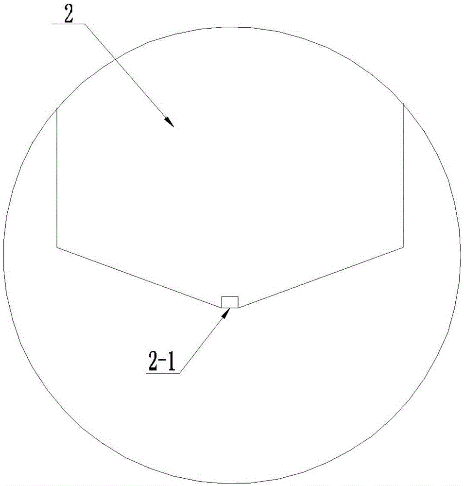
[0017] Such as Figure 1 to Figure 2 As shown, the glue injection device of temperature detection blind hole of the present invention comprises injection head 2, flexible pipe 3 and the conventional syringe 5 without needle, and the outer diameter of injection head 2 is less than the internal diameter of temperature detection blind hole 1, and the inner diameter of injection head 2 The front end is provided with a conical injection port 2-1, and the end of the injection head 2 is fixedly connected with the hose 3 and runs through it. The other end of the hose 3 is connected with a conventional syringe 4 without a needle and runs through it.

[0018] The injection head 2 is a rigid circular tube with a total length greater than or equal to 50 mm.

[0019] The outer diameter of the injection head 2 is smaller than the inner diameter of the temperature detecti...


PUM

PropertyMeasurementUnit
Lengthaaaaaaaaaa

Abstract

A glue injection device of a temperature detection blind hole belongs to the rail vehicle deep and thin blind hole special-purpose glue injection device field, and comprises an injection head, a flexible pipe and a conventional syringe not having a syringe needle. The external diameter of the injection head is less than the internal diameter of the temperature detection blind hole, the front end of the injection head is equipped with a conical glue injection port, the tail end of the injection head is fixedly connected and communicated with the flexible pipe, and the other end of the flexible pipe is connected and communicated with the conventional syringe not having the syringe needle. The beneficial effects of the present invention are that: the glue injection device of the temperature detection blind hole utilizes the conical glue injection port made of the flexible materials, such as the rubber, etc., as a glue injection part and a sealing part simultaneously, also can utilize the viscosity characteristic of a heat-conducting glue itself to form a temporary enclosed pressure environment while reducing the glue injection resistance, thereby quitting the injection head from the temperature detection blind hole automatically and slowly while finishing the glue injection process step by step, at the same time, guaranteeing the uniform glue injection and completely eradicating the bubble residual.

Description

technical field [0001] The invention belongs to the field of special glue injection devices for deep and thin blind holes of rail vehicles, and in particular relates to a glue injection device for temperature detection blind holes. Background technique [0002] Components that need to monitor temperature, such as axle boxes and gearboxes of rail vehicles, are equipped with blind holes for temperature detection with a large depth but a small diameter, so that they can be used to insert elongated temperature sensor probes. For example, the diameter of the temperature detection blind hole on a motor axle box is only 5.3mm, but its depth reaches 85mm. According to the design requirements, before inserting the temperature sensor, it is necessary to add thermal conductive adhesive to the bottom of this type of temperature detection blind hole to increase the uniformity of heat conduction. The injected thermal conductive adhesive needs to evenly fill the bottom cavity of the temper...

Claims


Application Information

Patent Timeline
IPC IPC(8): G01K1/14
Inventor 王海博
Owner CRRC CHANGCHUN RAILWAY VEHICLES CO LTD
Learn More