A kind of high temperature heavy oil viscosity reducer and its preparation method and application

A thick oil viscosity reducer and high temperature technology, which is applied in chemical instruments and methods, earthwork drilling and production, wellbore/well components, etc., can solve the problems of low steam volume sweep coefficient, high steam injection pressure, and short thermal recovery cycle , to achieve excellent emulsifying ability, increased sweep volume, and good salt tolerance

Active Publication Date: 2022-08-02
DESHI ENERGY TECH GRP CO LTD +1
View PDF6 Cites 0 Cited by
  • Summary
  • Abstract
  • Description
  • Claims
  • Application Information

AI Technical Summary

Problems solved by technology

[0003] However, in the process of steam injection production, on the one hand, due to the difference in viscosity between steam and crude oil, the steam injection pressure is high and the steam volume sweep coefficient is low; Increase again, resulting in shorter thermal recovery cycle and low mining efficiency

Method used


Image

  • A kind of high temperature heavy oil viscosity reducer and its preparation method and application
  • A kind of high temperature heavy oil viscosity reducer and its preparation method and application
  • A kind of high temperature heavy oil viscosity reducer and its preparation method and application

Examples


Embodiment 1

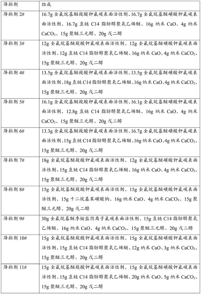
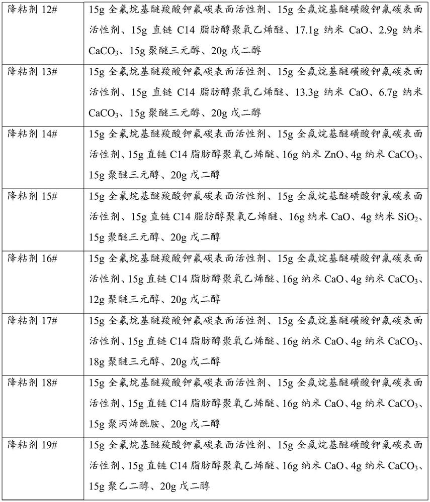
[0051] Example 1 Viscosity reducer 1#

[0052] Viscosity reducer 1# contains the following components by weight: 15g potassium perfluoroalkyl ether carboxylate fluorocarbon surfactant, 15g potassium perfluoroalkyl ether sulfonate fluorocarbon surfactant, 15g linear C14 fatty alcohol polyoxygen Vinyl ether, 16g nano-CaO, 4g nano-CaCO 3 , 15g polyether triol, 20g pentanediol.

[0053] The preparation method of viscosity reducer 1# comprises the following steps:

[0054] The above components are added to the stirring reaction kettle in proportion, stirred for 2 hours, and mixed evenly to obtain viscosity reducer 1#.

Embodiment 2

[0055] Example 2 Viscosity reducer 2#-19#

[0056] According to the preparation method of Example 1, viscosity reducers 2#-19# of different types and contents are provided, as shown in Table 1 for details.

[0057] Table 1

[0058]

[0059]

experiment example 1

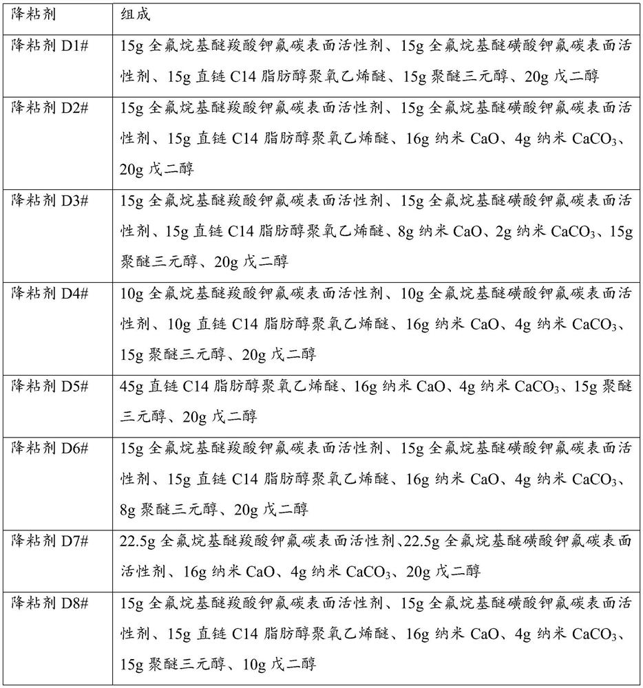
[0065] The temperature resistance and salt resistance of the obtained high-temperature heavy oil viscosity reducer were tested by the following methods, and the test results are shown in Table 3:

[0066] Crude oil used for testing: crude oil from a block in Shengli Oilfield (viscosity is 16750mPa·S at 50℃, density is 0.9921g / cm) 3 ).

[0067] Determination of viscosity reduction rate at different temperatures: first use a rotational viscometer to measure the initial viscosity of the heavy oil, then add 60g of viscosity reducer to the reaction kettle, put it at a temperature of 50°C to 350°C for 24 hours, take it out, and cool it. The viscosity reducer at 50°C was added to 140 g of heavy oil, and after stirring and emulsification for 20 minutes, the viscosity of the heavy oil after the reaction was measured with a rotational viscometer, and the viscosity reduction rate of the viscosity reducer to the heavy oil was calculated.

[0068] Determination of salt resistance: in the ...


PUM

PropertyMeasurementUnit
viscosityaaaaaaaaaa
densityaaaaaaaaaa
viscosityaaaaaaaaaa

Abstract

The application discloses a high-temperature heavy oil viscosity reducer and a preparation method and application thereof, belonging to the field of oilfield exploitation, and comprising the following raw material components in parts by weight: 35-50 parts of surfactant, 15-25 parts of nano-adjuvant , 12 to 18 parts of polymer additives and 16 to 24 parts of small molecular polyols; wherein, the small molecular polyols are selected from C3-C8 linear hydrocarbon polyols, and the nanometer additives are selected from nano-CaO, Nano ZnO, Nano CaCO 3 or nano-SiO 2 At least one of; the polymer auxiliary is selected from at least one of polyether polyol, polyester polyol or polyacrylamide. The high temperature heavy oil viscosity reducer has excellent emulsifying ability, strong penetrating ability and large sweep volume, which can significantly reduce the viscosity of heavy oil and greatly improve the recovery factor of heavy oil.

Description

technical field [0001] The application relates to a high-temperature heavy oil viscosity reducer, a preparation method and application thereof, and belongs to the field of oilfield exploitation. Background technique [0002] As most production wells have been exploited for many years, the continuous extraction of light components in the reservoir increases the viscosity of underground crude oil, and the proportion of heavy oil increases. Heavy oil has the characteristics of high density, high viscosity, high content of colloidal asphaltenes, and poor fluidity, so the recovery factor is low. At present, the development method of heavy oil is mainly thermal recovery, including technologies such as steam huff and puff, steam flooding, combustion of oil layers and steam-assisted gravity drainage. Among them, steam huff and puff and steam flooding technologies are relatively mature and have been widely used in heavy oil production. [0003] However, in the process of steam inje...

Claims


Application Information

Patent Timeline
Patent Type & Authority Patents(China)
IPC IPC(8): E21B43/24C09K8/584C09K8/592
CPCC09K8/584C09K8/592C09K2208/10
Inventor 崔仕章宋新旺侯云福王黎明郭鑫刘小芳马丽杨金兴
Owner DESHI ENERGY TECH GRP CO LTD
Why Eureka
Try Eureka