Radar angle measurement method

A radar and angle measurement technology, applied in the field of radar, can solve the problems of increasing angle measurement error, limited angle range of the target to be measured, etc., and achieve the effect of reducing the influence of noise on the signal

Active Publication Date: 2015-10-28
XIAMEN UNIV
View PDF4 Cites 12 Cited by
  • Summary
  • Abstract
  • Description
  • Claims
  • Application Information

AI Technical Summary

Problems solved by technology

There are two main disadvantages in the traditional phase comparison method for angle measurement: one is that when the angle of the target to be measured increases, the angle measurement error also increases. In order to ensure a certain angle measurement accuracy, the range of the angle of the target to be measured is limited; In the angle measurement range, when the ratio of the antenna spacing to the radar wavelength increases to a certain extent, the Δφ value may exceed 2π, at this time Δφ=2πN+ψ, where N is an integer, ψ<2π, and the actual reading of the phase comparison device is the value of ψ
Since the value of N is unknown, the real value of Δφ cannot be determined, and there will be a problem of multi-value

Method used


Image

  • Radar angle measurement method
  • Radar angle measurement method
  • Radar angle measurement method

Examples


Embodiment Construction

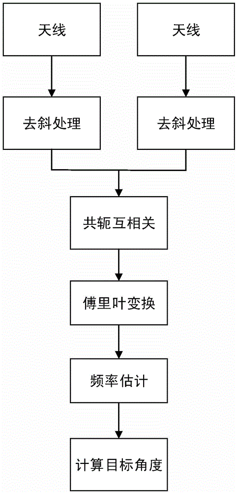
[0018] Such as figure 1 As shown, a method for radar angle measurement of the present invention specifically comprises the following steps:

[0019] Step 1. Suppose there is a target, the target is composed of 13 ideal point targets, the real angle of the target is 30°, the distance between the target and the radar is 2000m, the radial velocity of the target relative to the radar is 50m / s, and the signal-to-noise ratio The SNR is taken as 10dB. After the radar detects the target, the radar transmits a linear up-frequency modulation signal S(t): S(t)=cos(2πf 0 t+πkt 2 +φ 0 ), where f 0 is the initial frequency of the FM signal, take 77GHz, φ 0 is the initial phase of the FM signal, and k is the FM slope of the FM signal: Where BW is the bandwidth of the chirp signal, which is 1GHz, and T is the duration of the chirp signal, which is 20us;

[0020] The linear frequency modulation signal transmitted by the radar can be either an up frequency modulation signal or a down fr...


PUM


Abstract

The invention discloses a radar angle measurement method. After a radar detects a target, the radar emits a chirp signal, the chirp signal is reflected by the target, two reception antennas receive echo signals respectively, and the echo signals are obtained. The emission signal is employed as a reference signal, the two echo signals are subjected to dechirp processing, namely, the reference signal and the echo signals are subjected to slip frequency processing, two signals after dechirp processing are obtained, the two signals after dechirp processing are subjected to conjugate cross-correlation operation, a conjugate cross-correlation function is obtained, a frequency value corresponding to a position of a highest spectrum peak is estimated, and according to the linear relation of the frequency value and wave path difference of the echo signals received by the two reception antennas respectively and a trigonometric function relation of the wave path difference and the spacing between the two reception antennas, the angle of the target is calculated and obtained. Through the method, the angle measurement errors can be reduced, the angle measurement precision is raised, and the multi valuedness problem of angle measurement results is avoided.

Description

technical field [0001] The invention relates to the technical field of radar, in particular to a method for measuring angles by radar. Background technique [0002] Angle measurement refers to the determination of the pitch angle and azimuth angle of the target, which is an important part of target orientation. [0003] The traditional phase comparison method uses the phase difference between the echo signals received by two antennas to measure the angle. figure 2 It is a simulation diagram of the working principle of the receiving antenna when the radar uses the traditional phase comparison method to measure the angle. The distance between the two receiving antennas is d, which leads to the time difference between the echo signal reaching the two receiving antennas. Therefore, the echo signals received by the two receiving antennas have a wave path difference ΔR, that is, the phase difference of the two echo signals is Δφ. Let θ be the angle to be measured, then we can ge...

Claims


Application Information

Patent Timeline
IPC IPC(8): G01S13/06
CPCG01S13/06
Inventor 邓振淼张贻雄刘启凡洪汝佳潘萍平
Owner XIAMEN UNIV
Why Eureka
Try Eureka