
RF signal phase shifting network

A phase-shifting network and radio frequency signal technology, applied in the field of communications, can solve the problems of large phase-shifting errors of multi-frequency signals, and achieve the effects of improving use efficiency, convenient debugging and reducing errors

Active Publication Date: 2015-10-28
HARXON CORP
View PDF2 Cites 6 Cited by
  • Summary
  • Abstract
  • Description
  • Claims
  • Application Information

AI Technical Summary

Problems solved by technology

[0004] Based on this, it is necessary to provide a radio frequency signal phase shifting network to solve the problem that the traditional phase shifting network has a large phase shifting error for multi-frequency signal. The radio frequency signal phase shifting network uses a compensation phase shifting circuit to compensate The error caused by the phase shifting of the multi-frequency point signal by the circuit is used to reduce the error caused by the phase shifting of the multi-frequency point signal by the radio frequency signal phase shifting network, thereby improving the axial ratio, gain and other indicators of the circularly polarized antenna

Method used


Image

  • RF signal phase shifting network

Examples


Embodiment Construction

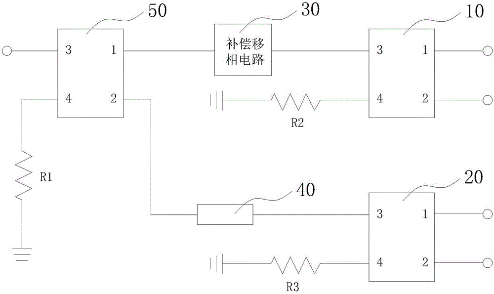
[0027] figure 1 A circuit diagram of the RF signal phase shifting network is shown. Such as figure 1 As shown, the RF signal phase shifting network includes a first phase shifter 10 , a second phase shifter 20 , a third phase shifter 50 , a compensation phase shifting circuit 30 , and a microstrip phase shifting circuit 40 .

[0028] Wherein, the first phase shifter 10, the second phase shifter 20, and the third phase shifter 50 are respectively used for phase shifting the input signal, and each includes a first port, a second port, a third port, and a fourth port .

[0029] The first phase shifter 10, its first port and second port are respectively used to input or output the first phase signal and the second phase signal, the third port is connected to the compensation phase shifting circuit 30, and the fourth port is connected to the matching load R2 .

[0030] The second phase shifter 20, its first port and second port are respectively used to input or output the third...


PUM


Abstract

An RF signal phase shifting network comprises the components of a first phase shifter, a second phase shifter, a third phase shifter, a compensating phase-shifting circuit and a microstrip phase-shifting circuit; wherein the first phase shifter, the second phase shifter and the third phase shifter can perform phase shifting on an input signal; the first phase shifter, the second phase shifter and the third phase shifter respectively comprise a first port, a second port, a third port and a fourth port. According to the RF signal phase shifting network, the compensating phase-shifting circuit is used for compensating a phase difference which is caused by the microstrip phase-shifting circuit to multiple-frequency-point signal phase shifting; an error of the whole RF signal phase shifting network to multiple-frequency-point signal phase shifting can be reduced; and phase flatness is reduced, thereby satisfying requirements for multiple navigation systems and broadband applications in a circular polarized antenna.

Description

technical field [0001] The invention relates to the technical field of communication, in particular to a radio frequency signal phase-shifting network. Background technique [0002] Because circularly polarized antennas can receive incoming waves with any polarization and have the orthogonality of rotation, circularly polarized antennas have important applications in communications, radar, electronic countermeasures, and GPS. Circularly polarized antennas generally synthesize or decompose circularly polarized signals by a phase-shifting network, and the phase-shifting network is usually composed of a 90° bridge phase-shifting circuit and a 90° microstrip phase-shifting circuit. [0003] The 90° bridge phase shifting circuit can shift the phase by 90° with high precision in a wide frequency band. Generally speaking, within the range of 1200MHz-1600MHz, it can meet the requirement of phase shifting of 90±3°, and the phase flatness is 3°. The error is lower. The 90° microstri...

Claims


Application Information

Patent Timeline
Patent Type & Authority Applications(China)
IPC IPC(8): H01P1/18H01Q3/34H01Q23/00
Inventor 王春华吴文平刘超
Owner HARXON CORP
Learn More