
A double-stator rotating electrical machine

A technology of rotating electrical machines and double stators, applied in electrical components, electromechanical devices, magnetic circuit shape/style/structure, etc., can solve the problems of reducing the reliability of permanent magnet motors, increasing copper loss of stator windings, and reducing the efficiency of permanent magnet motors.

Active Publication Date: 2018-01-30
舜驱动力科技(南通)有限公司
View PDF5 Cites 0 Cited by
  • Summary
  • Abstract
  • Description
  • Claims
  • Application Information

AI Technical Summary

Problems solved by technology

However, on the one hand, the field weakening is still not enough to support the large speed range required by electric vehicles, and the existence of the direct axis component of the stator current greatly increases the copper loss of the stator winding, reducing the efficiency of the permanent magnet motor; In the process of magnetic speed expansion, it is inevitable that the permanent magnet steel will be more or less demagnetized, which reduces the reliability of the permanent magnet motor

Method used

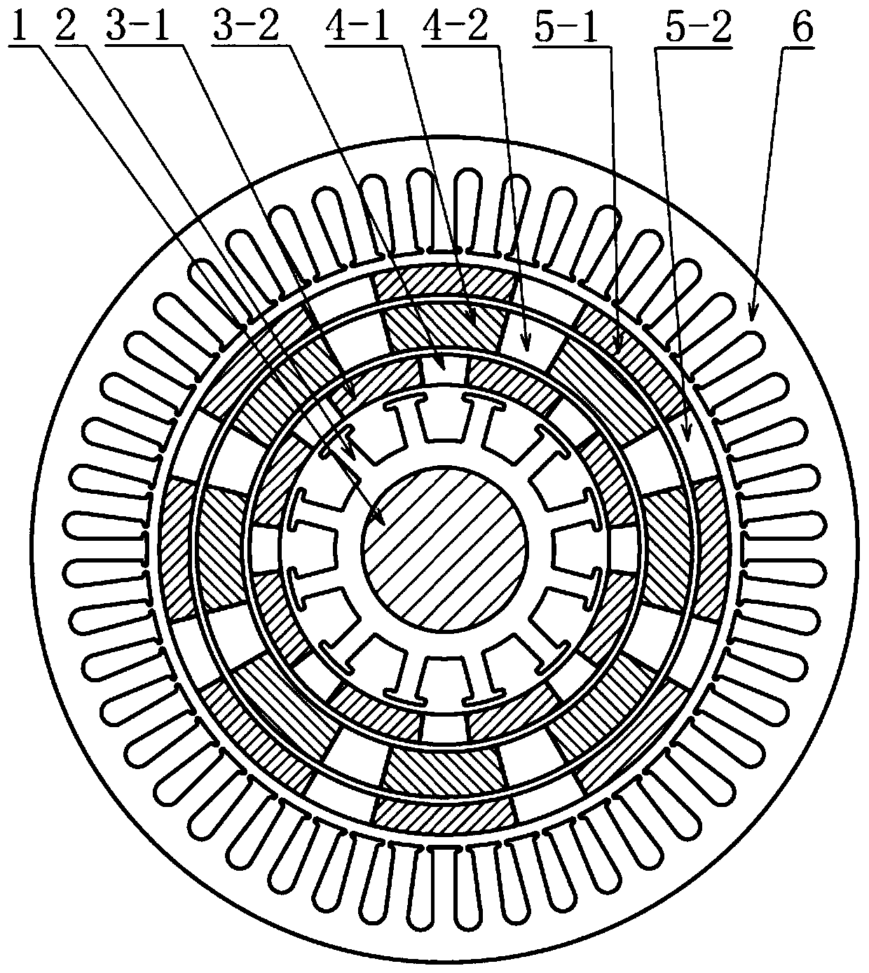
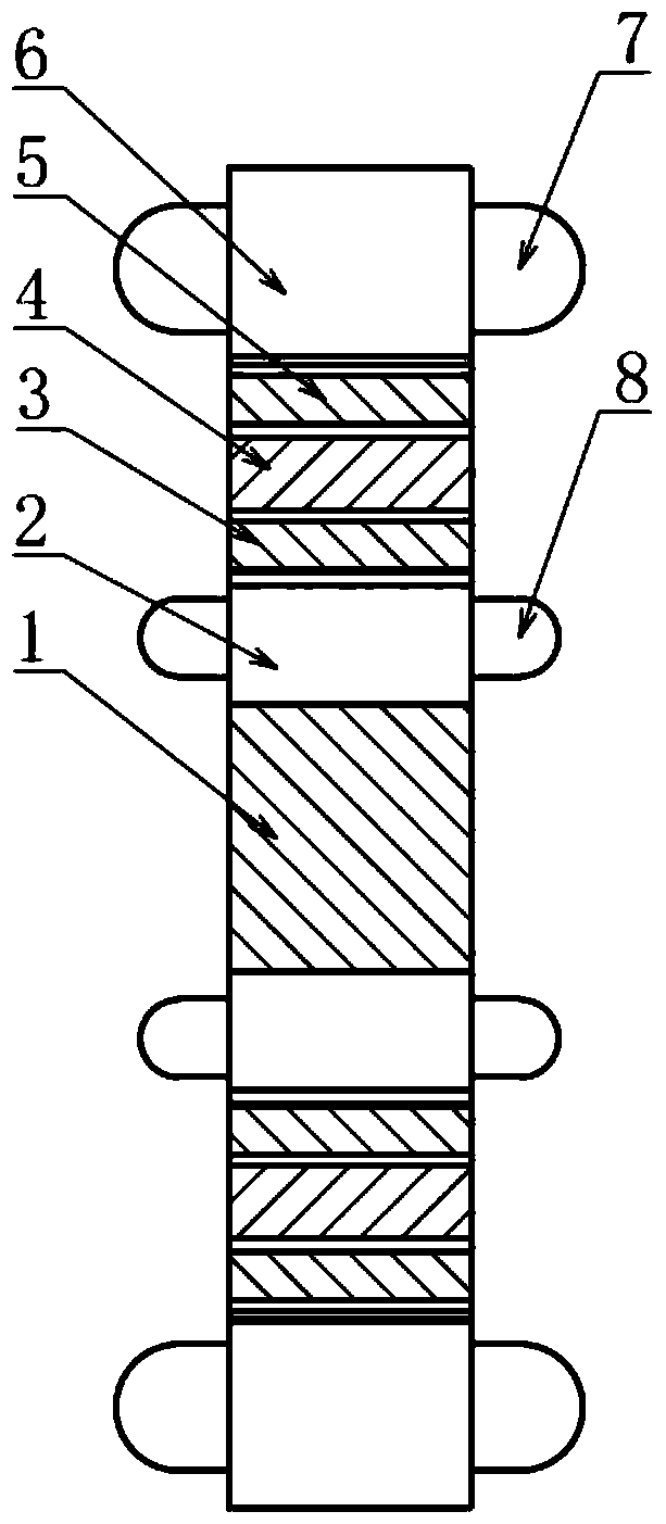
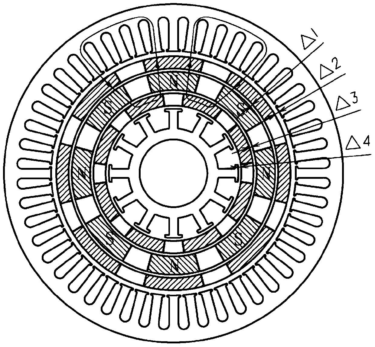

Image

  • A double-stator rotating electrical machine
  • A double-stator rotating electrical machine
  • A double-stator rotating electrical machine

Examples


Embodiment Construction

[0020] The present invention will be described in further detail below in conjunction with the accompanying drawings and embodiments. It should be understood that the specific embodiments described here are only used to explain the present invention, but not to limit the present invention. In addition, it should be noted that, for the convenience of description, the drawings only show some but not all structures related to the present invention, and the drawings are only for the purpose of illustration, and are not drawn according to the original scale.

[0021] Such as figure 1 As shown, this embodiment provides a double-stator rotating electrical machine, including a rotating shaft 1 arranged along the rotating axis of the rotating electrical machine, an inner stator core 2, an outer stator core 6 and a permanent magnet rotor 4 between the inner and outer stator cores. Among them, the permanent magnet rotor 4 is composed of the permanent magnet steel 4-1 on the permanent ma...


PUM


Abstract

The invention discloses a double-stator rotating electrical machine, which comprises a rotating shaft arranged along the rotating axis of the rotating electrical machine, an inner stator iron core, an outer stator iron core and a permanent magnet rotor located between the inner and outer stator iron cores. Among them, the permanent magnet rotor is composed of permanent magnet steel and non-magnetic parts; there is an inner magnetic field modulation ring between the permanent magnet rotor and the inner stator core, an outer magnetic field modulation ring between the permanent magnet rotor and the outer stator core, and an inner magnetic field modulation ring. Both the outer and outer magnetic field modulation rings are composed of a magnetically conductive part and a magnetically non-conductive part; the inner magnetic field modulation ring, the permanent magnet rotor and the outer magnetic field modulation ring can rotate relatively. The invention overcomes the problem of difficult adjustment of the magnetic field of traditional permanent magnet motors by adjusting the relative positions of the inner and outer magnetic field modulation rings and the permanent magnet rotor, and not only meets the requirements of low speed and high torque, but also expands the operating range of the motor at high speed. Improved power output characteristics over the full speed range.

Description

technical field [0001] The invention relates to the technical field of rotating electrical machines, in particular to a double-stator rotating electrical machine. Background technique [0002] With the development of motor technology and permanent magnet materials, rotating permanent magnet motors have been widely used in electric vehicle drive systems due to their advantages of high efficiency, high power density, and high power factor. The driving motor of new energy vehicles generally needs to run at variable speeds. At low speeds, it needs low-speed high-torque output; at high speeds, it needs to maintain constant power. Low-speed high-torque can meet the start-up of the whole vehicle, such as acceleration and climbing. The high-speed constant power can meet the maximum speed requirement of the whole vehicle, as well as overtaking at high speed. [0003] However, traditional permanent magnet motors (surface-mounted rotors or built-in rotors) mostly have a single-stator...

Claims


Application Information

Patent Timeline
Patent Type & Authority Patents(China)
IPC IPC(8): H02K16/04H02K1/06
Inventor 不公告发明人
Owner 舜驱动力科技(南通)有限公司
Learn More