Skeletal fixation device

A fixation device and fixation unit technology, applied in the direction of fixators, internal fixators, internal bone synthesis, etc., can solve the problems of being unable to adjust, stuck in the reaming part, and unable to be taken out, so as to enhance the support strength, increase the strength, and avoid scurrying effect

Active Publication Date: 2015-11-04
SPIRIT SPINE HLDG CORP
View PDF40 Cites 10 Cited by
  • Summary
  • Abstract
  • Description
  • Claims
  • Application Information

AI Technical Summary

Problems solved by technology

This type of operation method has the following disadvantages: the cancellous bone (cancellous bone) fragments crushed by the mechanical reamer during reaming often fall into the mechanical reamer, causing the mechanical reamer to get stuck. As a result, the reaming component cannot be retracted (returned to a contracted state), causing the entire mechanical reaming device to be stuck in the reaming part and cannot be removed
This type of operation has the following disadvantages: because the hole is not reamed first, the range of perfusion cannot be accurately controlled, so that the direction of perfusion after completion may be different from the doctor's original expectation; After the filling, it was found that the cladding unit did not fully support...

Method used


Image

  • Skeletal fixation device
  • Skeletal fixation device
  • Skeletal fixation device

Examples


Embodiment Construction

[0151] Hereinafter, specific embodiments of the bone fixation device of the present invention will be described with reference to the drawings.

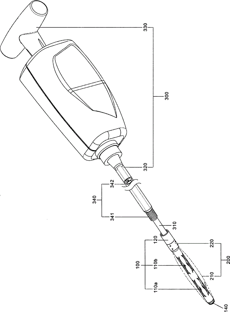
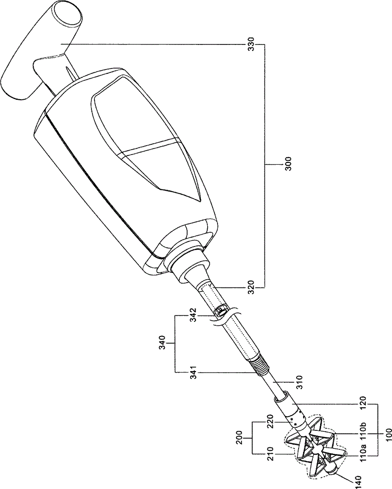
[0152] Figure 1a It is a schematic diagram of a preferred specific example of the bone fixation device of the present invention. Such as Figure 1a As shown, the expanded structure of the expanded unit 100 includes first expanded structures 110a and 110b, and the expanded structures 110a, 110b are in a contracted state. The covering unit 200 covers the deployment structures 110a, 110b of the deployment unit 100 by the spherical covering member 210, and also uses the covering unit 200 to block the broken bones in the vertebrae, so that the deployment unit 100 will not be affected by The bone fragments in the vertebrae get stuck, and it happens that the deployment unit 100 cannot be contracted to the collapsed state. The cladding unit 200 is fixedly connected with the deployment unit 100 by using the anchor at the connecting end 20...


PUM


Abstract

The invention provides a skeletal fixation device, comprising an expansion unit and a cladding unit. The expansion unit is provided with an expansion unit first end and an expansion unit second end, and comprises more than two expansion structures. The expansion structure can be switched between an expansion state and a contraction state. The cladding unit is used to wrap the expansion unit, and comprises a cladding unit first end and a cladding unit second end. The cladding unit first end is fixed on the expansion unit first end. The cladding unit second end is fixed on the expansion unit second end. When the skeletal fixation device is put in a bone, the expansion structure of the expansion unit is switched to the expansion state and stretches over the cladding unit, and a medical filler is filled in the cladding unit through the expansion unit second end.

Description

technical field [0001] The invention relates to a bone fixation device, in particular to a bone fixation device with a covering unit and an expansion unit capable of expanding and contracting. Background technique [0002] In the operation of pouring or inserting medical fillers into the bone, the current common surgical methods are as follows: [0003] Use mechanical reaming devices (such as US patents 20110196494, 20110184447, 20100076426, 20070067034, 20060009689, 20050143827, 20220052623, 6354995, 6676665) to ream the bone, create a space in the bone, take out the reaming device, , and then put into the cladding unit, and then perform the operation of pouring or stuffing the medical filler. This type of operation method has the following disadvantages: the cancellous bone (cancellous bone) fragments crushed by the mechanical reamer during reaming often fall into the mechanical reamer, causing the mechanical reamer to get stuck. As a result, the reaming component cannot...

Claims


Application Information

Patent Timeline
IPC IPC(8): A61B17/68A61B17/56
Inventor 许世雄林冠谷林士闳卢士钧
Owner SPIRIT SPINE HLDG CORP
Why Eureka
Try Eureka