Centrifugal polishing machine

A polishing machine and centrifugal technology, which is applied to surface polishing machine tools, grinding/polishing equipment, and parts of grinding machine tools, can solve the problems of high manufacturing and maintenance costs, low economic utilization, and low polishing efficiency, and achieve The effect of low manufacturing maintenance cost, high economic utilization rate and high polishing efficiency

Inactive Publication Date: 2015-11-04
CHANGZHOU BOMEI NEW MATERIAL TECH
View PDF6 Cites 4 Cited by
  • Summary
  • Abstract
  • Description
  • Claims
  • Application Information

AI Technical Summary

Problems solved by technology

However, most existing polishing machines have some deficiencies in structural design, complex structure, high manufacturing and maintenance costs, low polishing efficiency, and low economic utilization rate, which cannot meet the requirements of polishing manufacturers for low cost and high efficiency.

Method used


Image

  • Centrifugal polishing machine

Examples


Embodiment Construction

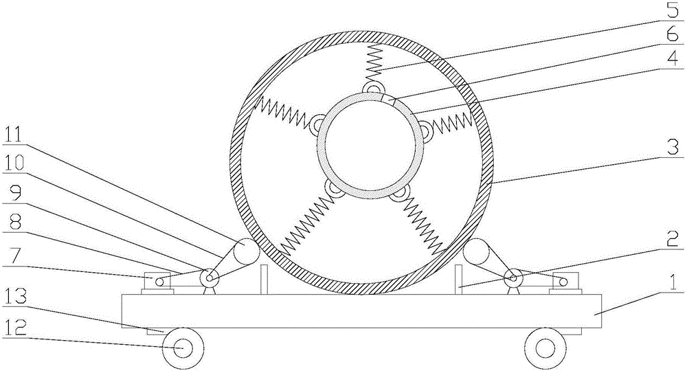
[0012] The present invention is described in further detail now in conjunction with accompanying drawing. These drawings are all simplified schematic diagrams, which only illustrate the basic structure of the present invention in a schematic manner, so they only show the configurations related to the present invention.

[0013] Such as figure 1 The centrifugal polishing machine of the present invention shown includes a support plate 1, and the upper surface of the support plate 1 is symmetrically provided with two spacer posts 2 and a drum 3 movable between the two spacer post 2, and the drum 3 A polishing barrel 4 is installed eccentrically in the center, and the roller barrel 3 and the polishing barrel 4 are connected by a plurality of springs 5 ​​with different lengths, and the side wall of the polishing barrel 4 is provided with an entrance 6 in which workpieces can be placed; The upper surface of the support plate 1 is also symmetrically provided with two driving mechani...


PUM


Abstract

The invention relates to the technical field of mechanical equipment, in particular to a centrifugal polishing machine. The machine comprises a supporting plate. The upper surface of the supporting plate is symmetrically provided with two limiting columns and a roller movably arranged between the two limiting columns. The roller is internally provided with a polishing barrel which is eccentrically arranged with the roller. The roller and the polishing barrel are connected through a plurality of springs different in length. The side wall of the polishing barrel is provided with an inlet capable of allowing a workpiece to be contained inside. The upper surface of the supporting plate is further symmetrically provided with two drive mechanisms used for driving the roller to roll. The centrifugal polishing machine is low in cost, high in polishing efficiency and capable of being widely used on various occasions where polished workpiece products are needed.

Description

technical field [0001] The invention relates to the technical field of mechanical equipment, in particular to a centrifugal polishing machine. Background technique [0002] In the molding process of most of the existing workpieces, sometimes in order to meet specific smoothness requirements, it usually needs to be processed with the help of some professional equipment. Polishing machine is one of these professional equipments. Polishing machine is also called grinding machine, which is often used for mechanical grinding, polishing and waxing. However, most of the existing polishing machines have some deficiencies in structural design, complex structures, high manufacturing and maintenance costs, low polishing efficiency, and low economic utilization, which completely cannot meet the requirements of polishing manufacturers for low cost and high efficiency. Contents of the invention [0003] The technical problem to be solved by the present invention is: in order to solve t...

Claims


Application Information

Patent Timeline
Patent Type & Authority Applications(China)
IPC IPC(8): B24B31/02B24B47/12
CPCB24B31/02B24B47/12
Inventor 刘鲸朱加尖刘春林
Owner CHANGZHOU BOMEI NEW MATERIAL TECH
Why Eureka
Try Eureka