
Magnetic coupling propulsion system and its application in ship propulsion

A technology of propulsion system and magnetic coupling, which is used in transmission devices with synchronous propulsion components, water action propulsion elements, etc., can solve the problems of ship net interference, large initial investment, increase in volume and weight of the propulsion system, and achieve vibration and noise. The effect of reducing, improving utilization, and saving space

Active Publication Date: 2017-08-15
JIANGSU MAGNET VALLEY TECH
View PDF8 Cites 0 Cited by
  • Summary
  • Abstract
  • Description
  • Claims
  • Application Information

AI Technical Summary

Problems solved by technology

However, this electric propulsion method still faces the following problems: First, generators, frequency converters and propulsion motors need to be added, which not only requires a large initial investment and low efficiency, but also greatly increases the volume and weight of the propulsion system
In addition, when the frequency converter is working, it will generate harmonics, which will interfere with the ship network

Method used


Image

  • Magnetic coupling propulsion system and its application in ship propulsion
  • Magnetic coupling propulsion system and its application in ship propulsion
  • Magnetic coupling propulsion system and its application in ship propulsion

Examples


Embodiment 1

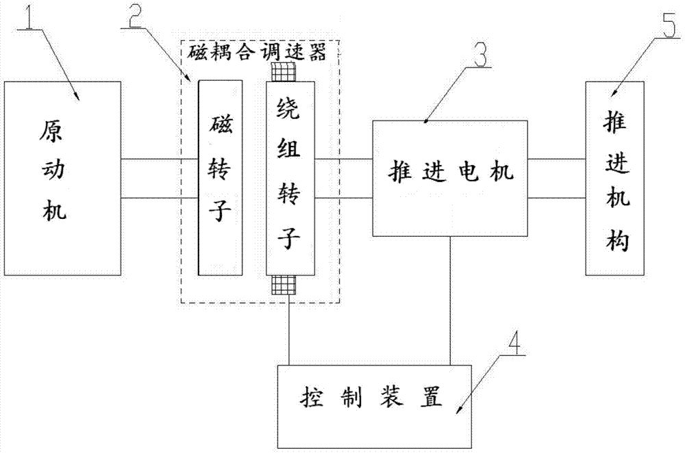
[0038] This embodiment provides a magnetic coupling propulsion system for ship propulsion, the structure is as follows figure 2 As shown, it includes a prime mover 1 , a magnetic coupling governor 2 , a propulsion motor 3 , a control device 4 and a propulsion mechanism 5 . Prime mover 1 is that the engine can be a fuel engine, a steam turbine or even an electric motor, and the original power system can be used. The prime mover here can run at a constant speed to make it work under the optimal working condition, with the highest combustion efficiency and energy Highest utilization rate. The magnetic coupling speed governor 2 includes a magnetic rotor and a winding rotor capable of mutual induction. The magnetic rotor and the winding rotor are arranged relative to each other without contact, and can induce mutual induction. The input shaft of the magnetic coupling speed governor 2 is connected to the magnetic rotor, and the output shaft is connected to the winding rotor. . Th...

Embodiment 2

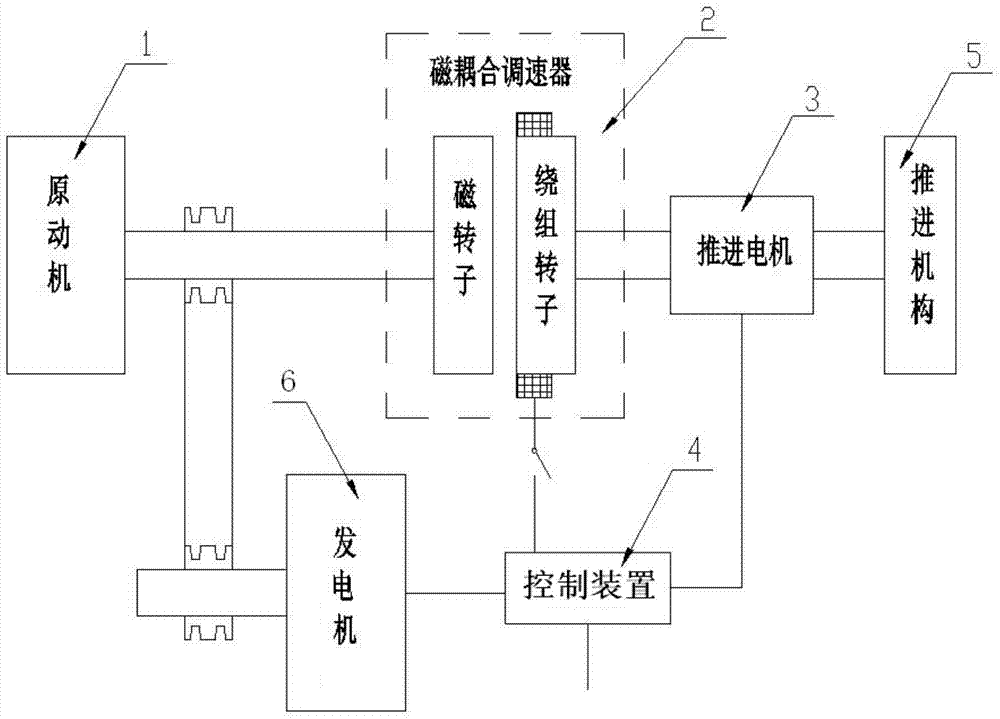
[0046] Another implementation is provided in this embodiment. When the capacity of the auxiliary propulsion motor is expanded, two propulsion mechanisms can be designed to serve as backups for each other or be divided into main and auxiliary propulsion mechanisms to work together. At this time, the structure of the magnetic coupling propulsion system of the ship is as follows:

[0047] The ship magnetic coupling propulsion system in this embodiment, such as image 3 As shown, it includes a prime mover 1 , a magnetic coupling governor 2 , a propulsion motor 3 , a control device 4 and a propulsion mechanism 5 . The prime mover 1 includes an engine and a speed reducer. The magnetic coupling governor 2 includes a magnetic rotor and a winding rotor capable of mutual induction, and the propulsion mechanism 5 includes a first propulsion mechanism 51 and a second propulsion mechanism 52, wherein

[0048] The output shaft of the prime mover 1 is connected with the input shaft of the ...


PUM


Abstract

The invention provides a magnetic coupling propulsion system and its application in ship propulsion. The magnetic coupling propulsion system includes a prime mover, a magnetic coupling governor, a propulsion motor, a control device and a propulsion mechanism. The magnetic coupling governor The output shaft is connected to the input shaft of the propulsion motor, and the windings of the rotor of the magnetic coupling governor and the windings of the propulsion motor are respectively connected to the control device. In this solution, the prime mover can run at the optimal speed and at a constant speed. Since the magnetic coupling governor can adjust the output power and torque, it can make the prime mover run at a constant speed and keep it in the optimal operating state, improving the efficiency of the prime mover. motivational efficiency. Among them, the magnetic coupling governor generates electric energy while transmitting torque, and the electric energy provides power for the propulsion motor, which improves the utilization rate of energy as a whole. Since the electric energy required by the propulsion motor is generated by the magnetic coupling governor itself, there is no connection with the ship network, and there is no problem of electromagnetic interference.

Description

technical field [0001] The invention relates to a power system, in particular to a magnetic coupling propulsion system. Background technique [0002] There are two main types of ship propulsion systems: mechanical propulsion and electric propulsion. Mechanical propulsion is a traditional propulsion method. From the successful sea trial of the steam engine ship "Claremont" designed by Fulton in 1807 to the present, mechanical propulsion has developed into a very mature technology, mainly including diesel engine propulsion, steam turbine propulsion and gas turbine propulsion. Due to the complex construction of the shafting system in the mechanical propulsion system and high alignment requirements, not only the production and processing requirements are high, but also the maintenance of the system is complex and requires a large amount of maintenance. In addition, the noise and vibration of the mechanical propulsion method is large, the efficiency is low when running at low sp...

Claims


Application Information

Patent Timeline
Patent Type & Authority Patents(China)
IPC IPC(8): B63H23/34
Inventor 陈超漆复兴
Owner JIANGSU MAGNET VALLEY TECH
Features
  • Generate Ideas
  • Intellectual Property
  • Life Sciences
  • Materials
  • Tech Scout
  • Unparalleled Data Quality
  • Higher Quality Content
  • 60% Fewer Hallucinations
Learn More