Container and cover

A container and container body technology, applied in transportation, packaging, closing, packaging, etc., can solve problems such as large errors, troublesome volume precision measurement operations, and problems that are easily overlooked by people

Active Publication Date: 2015-11-04
BEIJING RED SEA TECH
View PDF6 Cites 5 Cited by
  • Summary
  • Abstract
  • Description
  • Claims
  • Application Information

AI Technical Summary

Problems solved by technology

Due to the troublesome operation and large error of precise volume measurement, the concentration and o

Method used


Image

  • Container and cover
  • Container and cover
  • Container and cover

Examples


Embodiment 1

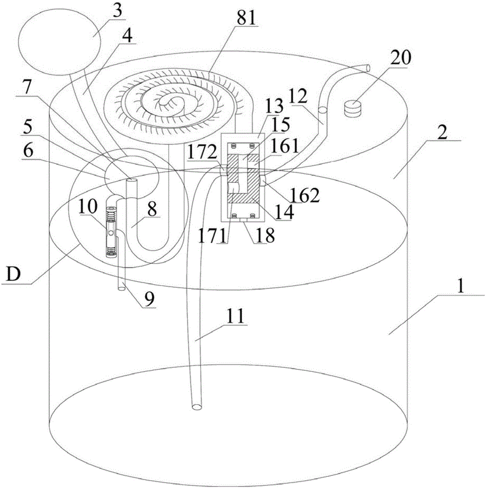
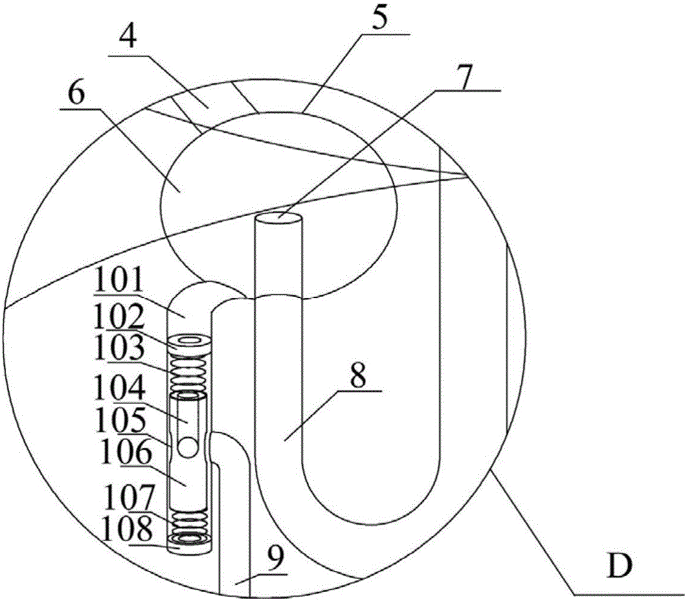
[0045] Such as figure 1 with figure 2 Shown is a container using the initial positioning system of the present invention according to Embodiment 1. The container as a whole includes a container body 1 and a top cover 2, and the upper part of the container body 1 is the top cover 2. The container body 1 contains most of the contents. Other components including variable pressure components, initial positioning device, metering channel 8, liquid taking channel 11, outflow channel 12 valves, etc. are all installed and fixed on the top cover 2. The top cover 2 also has a check valve 20 which only allows liquid and gas to enter the container body 1.

[0046] The pressure-changing component is a component that can pressurize and depressurize the reflux cavity 6, and includes an air bag 3 and a pressure-changing channel 4. The airbag 3 is located above the top cover 2 and is fixed on the top cover 2 through the pressure-changing channel 4. The initial positioning device includes a re...

Embodiment 2

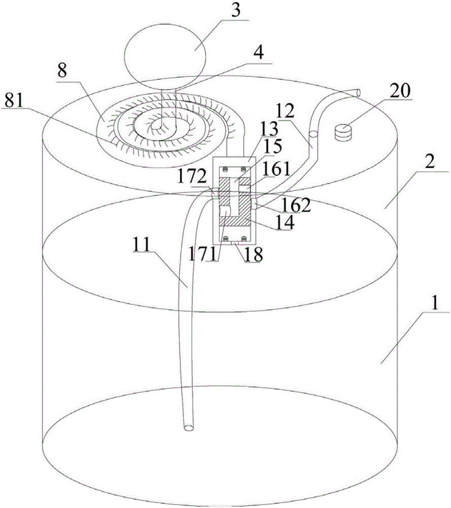
[0062] Such as image 3 Shown is a container according to the second embodiment. Compared with Embodiment 1, the container does not use the initial positioning device, and the pressure-changing channel 4 of the pressure-changing component is directly connected with the metering channel 8. The container also includes a container body 1 and a top cover 2 as a whole, and the upper part of the container body 1 is the top cover 2. Other components including variable pressure components, metering channel 8, liquid taking channel 11, outflow channel 12 valves, etc. are all installed and fixed on the top cover 2. The top cover 2 also has a check valve 20.

[0063] The initial section of the metering channel 8 communicates with the variable pressure channel 4, the middle section is a metering section with a metering scale 81, and the end is connected to a control valve composed of a valve body 13 and a spool 14 and communicates with the middle channel 15 in the spool 14. The valve body ...

Embodiment 3

[0068] Such as Figure 4 , Figure 5 Shown is a container using the initial positioning system of the present invention according to Embodiment 3. The container as a whole includes a container body 1 and a top cover 2, and the upper part of the container body 1 is the top cover 2. The container body 1 contains most of the contents. Other components including variable pressure components, initial positioning device, metering channel 8, liquid taking channel 11, outflow channel 12 valves, etc. are all installed on the top cover 2. The top cover 2 also has a check valve 20 which only allows liquid and gas to enter the container body 1.

[0069] The pressure-changing component is a component that can pressurize and depressurize the reflux cavity 6, and includes an air bag 3 and a pressure-changing channel 4. The airbag 3 is located above the top cover 2 and is fixed on the top cover 2 through the pressure-changing channel 4. The initial positioning device includes a return cavity ...


PUM


Abstract

The invention provides a container. The container comprises a container body and a cover and further comprises a variable-pressure part, a metering channel, a liquid taking channel and a flow-out channel. The head of the metering channel is communicated with the variable-pressure part. The tail of the metering channel is communicated with the flow-out channel and the liquid taking channel. A valve is arranged between the metering channel and the flow-out channel; and the valve is opened when the variable-pressure part is pressurized, and the valve is closed when the variable-pressure part is depressurized. A valve is arranged between the metering channel and the liquid taking channel or in the liquid taking channel; and the valve is opened when the variable-pressure part is depressurized, and the valve is closed when the variable-pressure part is pressurized. The metering channel, the liquid taking channel and the flow-out channel are fixed to the cover. The container is simple in structure, convenient to use and accurate in metering.

Description

Technical field [0001] The invention relates to a container and a cover on the container body, in particular to a container and a cover on the container body that have a metering function and realize liquid taking and use through pressure change. Background technique [0002] In today's life, people often use fluids, such as hand sanitizer, laundry detergent, disinfectant, shampoo, shower gel, toothpaste, soy sauce, vinegar, edible oil, liquid medicine, cosmetics, health care products, etc. However, although the containers for the above-mentioned products have various shapes, there are very few innovative structures, and there have been no major improvements for many years, and many of the problems that people have become accustomed to. [0003] For example, there is no container for quantitative removal in life. When people have to take out quantitatively, they often use other graduated containers to achieve quantitative take-out, and sometimes they still use a rough measurement ...

Claims


Application Information

Patent Timeline
IPC IPC(8): B65D47/22
Inventor 陈增新
Owner BEIJING RED SEA TECH
Why Eureka
Try Eureka