
Cloth delivery mechanism

A technology of cloth feeding mechanism and swivel box, which is applied to cloth feeding mechanism, sewing machine components, textiles and papermaking, etc., can solve the problem of reducing the contact area between teeth and presser foot, difficult to achieve precise consistency, and high processing cost of parts It can reduce the wrinkling of the fabric, facilitate installation and debugging, and improve the assembly efficiency.

Active Publication Date: 2015-11-04
BULLMER ELECTROMECHANICAL TECH
View PDF10 Cites 2 Cited by
  • Summary
  • Abstract
  • Description
  • Claims
  • Application Information

AI Technical Summary

Problems solved by technology

[0003] (1) The cloth feeding mechanism basically adopts two-degree-of-freedom dual-axis drive to realize the cloth feeding track. In order to ensure the coordination and synchronization of horizontal movement and vertical movement, installation and debugging are very cumbersome
[0004] (2) The cloth feed dog of the existing mechanism always has an inclination angle during the movement process, which reduces the contact area between the tooth and the presser foot, not only reduces the cloth feeding force, but also tends to break when sewing thin materials. wrinkle
[0005] (3) The cloth feeding mechanism contains many connecting rods, eccentric wheels and other parts. Not only the processing cost of the parts is high, but also the inertial vibration is large, and the vibration and noise are very large at high speed
[0006] (4) Even after a lot of debugging, it is difficult to achieve accurate consistency between the stitch lengths of forward and reverse stitches

Method used


Image

  • Cloth delivery mechanism
  • Cloth delivery mechanism
  • Cloth delivery mechanism

Examples


Embodiment Construction

[0028] The following will clearly and completely describe the technical solutions in the embodiments of the present invention with reference to the accompanying drawings in the embodiments of the present invention. Obviously, the described embodiments are only some, not all, embodiments of the present invention. Based on the embodiments of the present invention, all other embodiments obtained by persons of ordinary skill in the art without making creative efforts belong to the protection scope of the present invention.

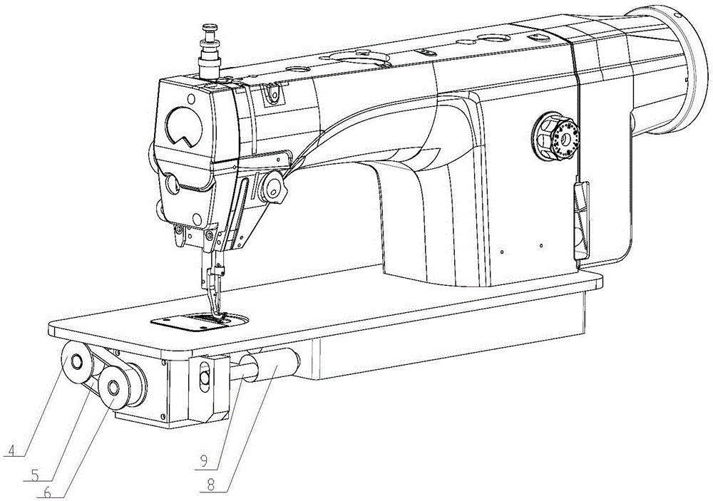
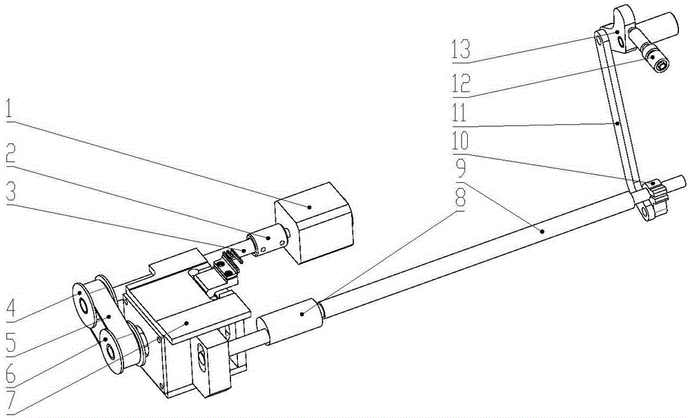
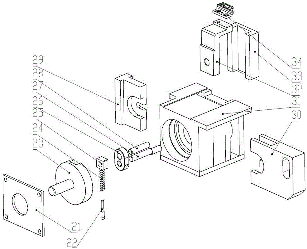
[0029] see Figure 1~5 The present invention provides a technical solution: a cloth feeding mechanism, including a swivel box and a cloth feeding mechanism; the swivel box includes a sealing plate 21, a spring pin 22, a turning groove 23, a spring 24, a slider 25, a Rod 26, inner rotor 27, outer rotor 28, fixed semi-rotary ring 29, sliding semi-rotary ring 30, swivel box body 31, tooth bracket 32, chute 33 and cloth feeding dog 34; said inner rotor 27 and oute...


PUM


Abstract

The invention discloses a cloth delivery mechanism which comprises a swivel case and a cloth delivery mechanism. An inner rotor and an outer rotor rotate in a rotary chute in the swivel case, a spring is connected with a slide block, and a fixed semi-swivel and a sliding semi-swivel are arranged on the two sides of the swivel case body. The chute is connected to one end of a tooth rack, and cloth delivery tooth are installed on the top of the tooth rack. A coupler is connected to a cloth delivery motor shaft and the cloth delivery shaft, a first synchronizing wheel is installed on the cloth delivery shaft, and a second synchronizing wheel is installed on the outer end of the swivel case. A synchronous belt winds on the second synchronizing wheel and the first synchronizing wheel, and a needle distance adjusting shaft is connected with the swivel case, and a needle distance adjusting rocking bar is arranged on the needle distance adjusting shaft. The needle distance adjusting shaft connects the needle distance adjusting rocking bar and a needle distance base, and same forward and backward needle distances are ensured. Wrinkling and skidding of cloth delivery can be minimized, vibration and noise during delivering cloth at high speed can be reduced, and working rotating speed is increased. The cloth delivery mechanism is easy to realize modular production and assembly, and assembly efficiency is improved.

Description

technical field [0001] The invention relates to the application field of a cloth feeding mechanism, in particular to a cloth feeding mechanism. Background technique [0002] On sewing machines or other mechanical equipment related to cloth production, the existing cloth feeding mechanism has the following disadvantages: [0003] (1) The cloth feeding mechanism basically adopts a two-axis drive with two degrees of freedom to realize the cloth feeding trajectory. In order to ensure the coordination and synchronization of the horizontal movement and the vertical movement, the installation and debugging are very cumbersome. [0004] (2) The cloth feed dog of the existing mechanism always has an inclination angle during the movement process, which reduces the contact area between the tooth and the presser foot, not only reduces the cloth feeding force, but also tends to break when sewing thin materials. wrinkle. [0005] (3) The cloth feeding mechanism includes many connecting ...

Claims


Application Information

Patent Timeline
IPC IPC(8): D05B27/02
Inventor 谭炜军
Owner BULLMER ELECTROMECHANICAL TECH
Learn More