Switching mechanism for translation system and rotating system

A technology of translation system and conversion mechanism, which is applied in the direction of mechanical equipment, engine components, machines/engines, etc., can solve problems such as complex system structure, and achieve the effect of simple structure and reasonable design

Inactive Publication Date: 2015-11-04
鲁斯嘉
View PDF1 Cites 0 Cited by
  • Summary
  • Abstract
  • Description
  • Claims
  • Application Information

AI Technical Summary

Problems solved by technology

However, its design requires a special control structure, and the entire system structure is complex

Method used


Image

  • Switching mechanism for translation system and rotating system
  • Switching mechanism for translation system and rotating system
  • Switching mechanism for translation system and rotating system

Examples


Embodiment

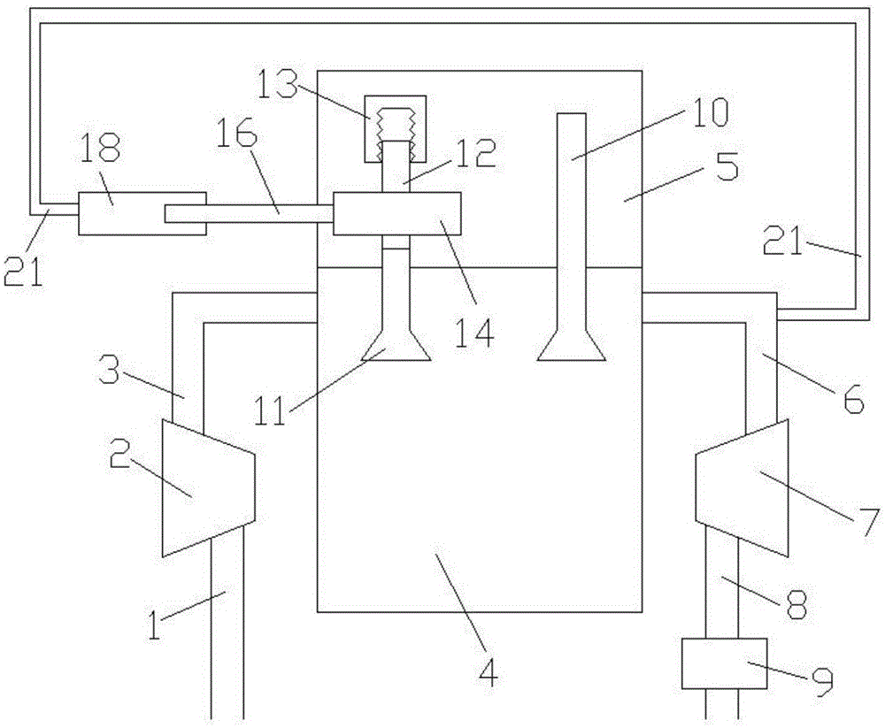
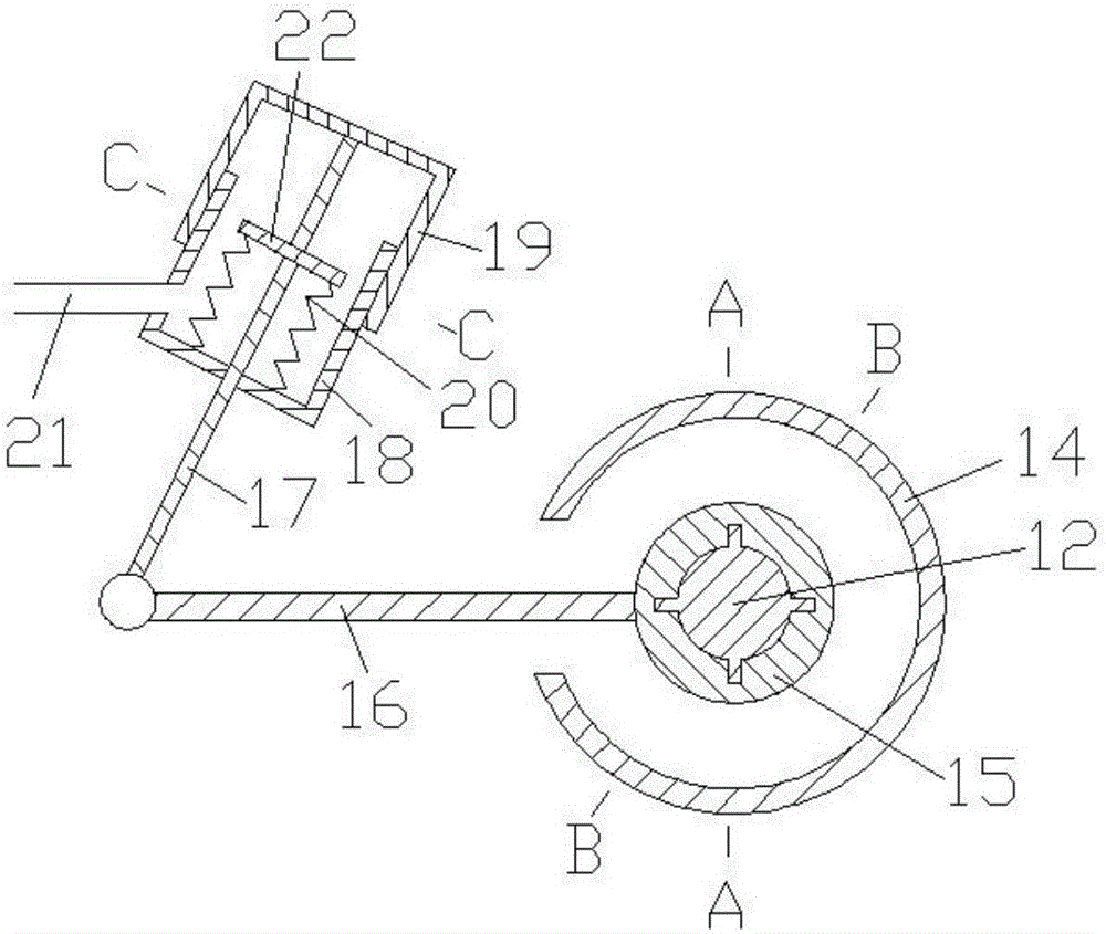
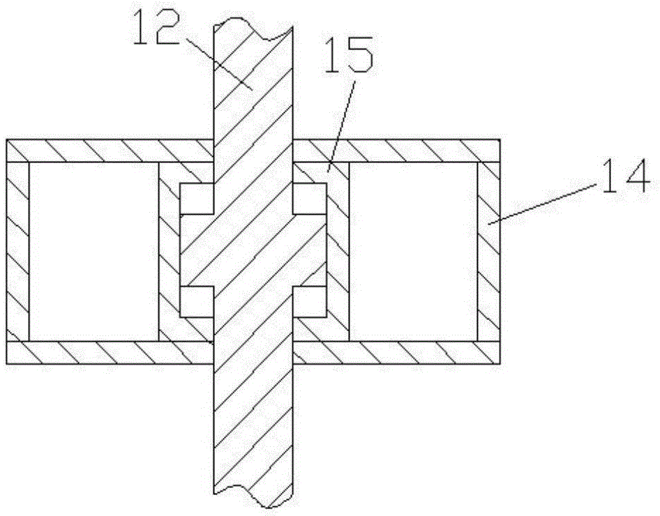
[0016] Examples of the present invention are Figure 1 to Figure 5 Shown, the present invention comprises compressor intake pipe 1, compressor 2, engine intake pipe 3, cylinder block 4, cylinder head 5, engine exhaust pipe 6, turbine 7, turbine exhaust pipe 8, catalytic bag 9, exhaust Door 10, intake valve lower section 11, intake valve middle section 12, intake valve upper section 13, first control chamber 14, rotating shaft 15, rotating rod 16, stretching rod 17, second control chamber lower body 18, second control chamber Cavity upper body 19, spring 20, connecting pipe 21, fixed plate 22, the air inlet and outlet of compressor 2 are connected with compressor inlet pipe 1 and engine inlet pipe 3 respectively, and the inlet and outlet of turbine 7 are respectively connected with engine exhaust pipe 6, The turbine exhaust pipe 8 is connected, the engine intake pipe 3 and the engine exhaust pipe 6 are connected to the cylinder block 4, the cylinder head 5 is arranged on the cy...


PUM


Abstract

The invention belongs to a switching mechanism for a translation system and a rotating system, belonging to the technical field of mechanical design. The switching mechanism comprises an air inlet door, control cavities, a rotating shaft, a rotating rod, a tension bar, a spring, a mobile object, a connecting pipe and a fixed plate, wherein four cavities are arranged in the rotating shaft, the middle section of the air inlet door is provided with four reinforcing ribs, and the four reinforcing ribs in the middle section of the air inlet door are respectively arranged in the four cavities of the rotating shaft; the second control cavity consists of a second control cavity lower body and a second control cavity upper body, the fixed plate is arranged in the second control cavity and is fixedly connected with the tension bar, and the lower wall surface of the second control cavity lower body is connected with the fixed plate through the spring; one end of the connecting pipe is communicated with the second control cavity, and the other end of the connecting pipe is communicated with an engine exhaust pipe. According to the switching mechanism provided by the invention, when pressure in the second control cavity is higher, the middle section of the air inlet door rotates clockwise, so that the valve stroke can be increased, and the air inflow of an engine can be increased; furthermore, the switching mechanism is reasonable in design and simple in structure, and is applicable to the design of a lift-continuously-variable system of the air inlet door.

Description

technical field [0001] The invention belongs to the technical field of internal combustion engines, and specifically relates to a conversion mechanism for a translation system and a rotation system that can realize continuously variable lift of an intake valve on the principle of aerodynamics. Background technique [0002] The valve lift of the traditional gasoline engine is fixed and invariable, that is, there is only one cam profile of the camshaft, which makes it impossible for the lift to make the engine respond well in both high-speed and low-speed areas. The valve lift or cam profile design of a traditional gasoline engine is a balanced choice for the engine under all operating conditions. As a result, the engine can neither get the best high-speed efficiency nor the best low-speed torque, but it can get The most balanced performance under all working conditions. The adoption of variable valve lift enables the engine to obtain the required valve lift in both high-spee...

Claims


Application Information

Patent Timeline
Patent Type & Authority Applications(China)
IPC IPC(8): F01L13/00F01L9/02F01L9/10
Inventor 鲁斯嘉朱澄玉
Owner 鲁斯嘉
Why Eureka
Try Eureka