Hydraulic combined engine

An engine and hydraulic technology, applied to machines/engines, mechanisms that generate mechanical power, mechanical equipment, etc., can solve the problems of no hydraulic self-powering cycle power generation device, no hydraulic device with high speed and high torque, etc., to save The motive force, the effect of saving fuel and reducing environmental pollution

Inactive Publication Date: 2015-11-04
王守玉
View PDF0 Cites 1 Cited by
  • Summary
  • Abstract
  • Description
  • Claims
  • Application Information

AI Technical Summary

Problems solved by technology

[0003] Currently on the market, there are rotary devices that output low speed and high torque, which have been widely used in hydraulic lifting and hois

Method used


Image

  • Hydraulic combined engine
  • Hydraulic combined engine
  • Hydraulic combined engine

Examples


Example Embodiment

[0019] The present invention will be further explained in conjunction with the drawings:

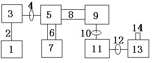
[0020] Such as figure 1 As shown, the hydraulic combination engine of the present invention consists of auxiliary power generation device 1, connecting cable 2, motor 3, flange 4, oil pump 5, oil pipe 6, oil tank 7, oil pipe 8, hydraulic motor 9, flange 10 , The speed increaser 11, the flange 12, the speed increaser 13, and the output shaft 14, which are characterized in that: the hydraulic motor 9 is connected with the speed increaser 11 and the speed increaser 13, and the auxiliary generator 1 is connected with the electric motor 2. The connection method is that the auxiliary generator 1 is connected to the electric motor 3 through the connecting cable 2, the electric motor 3 is connected to the oil pump 5 through the flange 4, the oil tank 7 is connected to the oil pump 5 through the oil delivery pipe 6, and the oil pump 5 is connected to the hydraulic motor 9 through the oil delivery pi...


PUM


Abstract

The invention relates to a hydraulic combined engine. The hydraulic combined engine consists of an auxiliary power generating device 1, a connecting cable 2, an electric motor 3, a flange plate 4, an oil pump 5, an oil conveying tube 6, an oil tank 7, an oil conveying tube 8, a hydraulic motor 9, a flange plate 10, a speed increaser 11, a flange plate 12, a speed increaser 13 and an output shaft 14. The hydraulic combined engine is characterized in that the hydraulic motor 9 is connected with the speed increaser 11 and the speed increaser 13. The auxiliary power generating device 1 is self-circulating power generating equipment, is low in consumption of external force and capable of independently generating power forworking. The hydraulic combined engine outputs high rotation speed and large torque power, can widely replace engines of a car, an agricultural vehicle, a gravity machine, a propeller-driven aircraft and a ship, also can be widely used for generating power, is especially suitable for fuel power generation, storage battery power generation, hydraulic power generation, nuclear power generation, and can be used for large-power generation of an electromechanical auxiliary power unit.

Description

Technical field [0001] The invention is a hydraulic combination engine, involving hydraulic combination high -power power generation, water conservancy hydraulic high -power power generation, wind power power generation, fuel hydraulic high -power power generation, battery hydraulic high -power power generation, nuclear power hydraulic high -power power generation, municipal electric hydraulic pressureGreat power generation and so on. [0002] Background technique [0003] At present, there are rotating devices with low speed and high torque, which have been widely used for hydraulic lifting and rolling machines, but no high -speed and large torque hydraulic device has been found, especially the hydraulic self -power supply cycle power generation device. Invention content [0004] The purpose of the present invention is to provide a hydraulic combination engine, which consists of auxiliary power generation device, hydraulic motor and the growth rate. It can transform the low spe...

Claims


Application Information

Patent Timeline
IPC IPC(8): F03G7/10F03G7/00
Inventor 王守玉
Owner 王守玉
Why Eureka
Try Eureka