
Compressor for combined screw rod

A compressor and screw technology, applied in the field of combined screw compressors, can solve the problems of high processing cost, high processing difficulty, long processing time, etc., and achieve the effects of high practicability, reduced processing difficulty, and reduced difficulty.

Inactive Publication Date: 2015-11-04
QUZHOU YIFAN DESIGN
View PDF4 Cites 1 Cited by
  • Summary
  • Abstract
  • Description
  • Claims
  • Application Information

AI Technical Summary

Problems solved by technology

[0010] The technical problem solved by the present invention is: in order to solve the technical defects of the prior art compressors such as complicated process, long processing time, high processing difficulty and high processing cost when processing the screw shaft, a compressor with a screw shaft is provided, especially a kind of Multi-piece quenched toothed sheet parts are inserted into the shaft, glued, superimposed and spot welded to form a combined screw shaft compressor, which achieves the technical purpose of low-cost, rapid manufacturing of high-physical performance compressors

Method used


Image

  • Compressor for combined screw rod
  • Compressor for combined screw rod
  • Compressor for combined screw rod

Examples


example 1

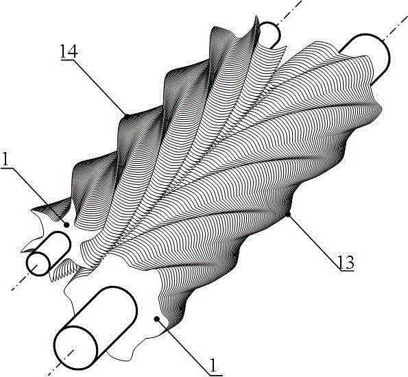
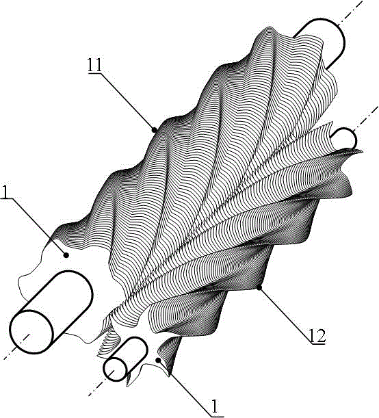
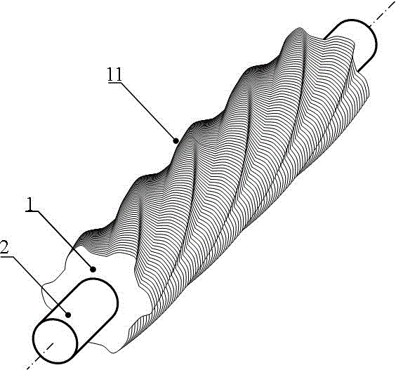
[0051] Example 1: Such as Figure 1 to Figure 15 As shown, the disclosed compressor with a combined screw includes a cylinder with a screw shaft in the cylinder. The screw shaft is a combined screw shaft of thin parts. The screw shaft also includes thin parts 1, shaft 2, and thin parts 1. The outside of the shaft 2 has a tooth bottom engagement part 7 and a tooth top engagement part 8. There is a shaft hole in the sheet part 1, and there is at least one tooth-shaped protrusion in the shaft hole. There is at least one spiral groove on the outside of the shaft 2. The sheet part 1 The number of tooth-shaped protrusions in the shaft hole is the same as the number of the outer spiral grooves of the shaft 2, and they are matched with each other. The outside of the shaft 2 is tightly and orderly sleeved with multiple sheets of parts 1, shaft 2 and multiple sheets The relative position between the parts 1 is fixed, and the gap between the shaft 2 and the multi-sheet parts 1 is filled w...

example 2

[0061] Example 2: Such as Figure 1 to Figure 15 And as shown in Example 1, a compressor with a combined screw is disclosed,

[0062] The glue adopts epoxy resin cement or quick-drying structural glue or metal structural glue.

example 3

[0063] Example 3: Such as Figure 1 to Figure 15 And as shown in Example 1, a compressor with a combined screw is disclosed,

[0064] Metal powder is mixed into the glue.


PUM


Abstract

The invention provides a compressor for a combined screw rod and particularly relates to a compressor for a combined screw rod shaft. A screw rod shaft body is formed in the mode that a plurality of quenched sheet parts with teeth are arranged on a shaft in a sleeving mode, stacked after being glued and spot-welded. The compressor comprises a cylinder, and the screw rod shaft is arranged in the cylinder. The screw rod shaft is a sheet part combined screw rod shaft. The screw rod shaft further comprises the sheet parts and the shaft. The outer side of each sheet part is provided with a tooth bottom engagement part and a tooth top engagement part. A shaft hole is formed in each sheet part, at least one tooth-shaped protrusion is arranged in each shaft hole, and at least one spiral groove is formed in the outer side of the shaft. The number of the tooth-shaped protrusions in the shaft holes of the sheet parts and the number of the spiral grooves in the outer side of the shaft are the same. The tooth-shaped protrusions are matched with the spiral grooves. The shaft is tightly sleeved with the sheet parts in order, the relative positions between the shaft and the sheet parts are fixed, and the gaps between the shaft and the sheet parts are filled with cured glue. The technical purpose of quickly manufacturing the compressor with high physical performance at a low cost is achieved.

Description

Technical field [0001] The invention relates to a compressor with a combined screw, in particular to a compressor with a combined screw in which a plurality of quenched sheet parts with teeth are sleeved into a shaft, glued, superimposed and spot welded to form a screw shaft body. Background technique [0002] Screw compressors, also called screw compressors, include screw air compressors and screw process compressors (vinyl chloride compressors, etc.). Screw compressors are divided into single screw compressors and twin screw compressors. Screw compressors use screw The shaft-shaped rotor rotates in the cylinder to compress and transport the medium. [0003] The screw compressor has high reliability, few parts and no wearing parts, so it runs reliably and has a long life. The main design life of the general screw compressor is up to 30 years; the operation and maintenance are convenient, the degree of automation is high, and the operator does not need to spend a long time Profess...

Claims


Application Information

Patent Timeline
Patent Type & Authority Applications(China)
IPC IPC(8): F04C18/16B23P15/00
Inventor 吴超
Owner QUZHOU YIFAN DESIGN
Learn More