
Microscope objective table based on specimen mobile control mechanism

A control mechanism and stage technology, applied in microscopes, optics, instruments, etc., can solve problems such as specimen movement, achieve the effects of reducing dependence, enhancing automatic control functions, and effectively and quickly adjusting

Inactive Publication Date: 2015-11-04
苏州南光电子科技有限公司
View PDF5 Cites 0 Cited by
  • Summary
  • Abstract
  • Description
  • Claims
  • Application Information

AI Technical Summary

Problems solved by technology

[0009] The technical problem to be solved by the present invention is to overcome the deficiencies of the prior art, provide a microscope stage based on the specimen movement control mechanism, and solve the problem that the position of the specimen holder can only be adjusted when the stage in the existing microscope is manually moved, The problem of driving the specimen to move

Method used


Image

  • Microscope objective table based on specimen mobile control mechanism

Examples


Embodiment 1

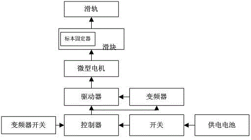
[0025] The microscope stage of this embodiment includes a stage body and a specimen holder set thereon, and also includes a specimen movement control mechanism that includes a power supply battery, a switch, a controller, a driver, a micro motor, The sliding rail and the sliding block, wherein the sliding rail is arranged on the surface of the stage body, the bottom of the sliding block is movably embedded in the sliding rail; the micro motor is fixedly arranged in the sliding block, and the sliding block The surface fixation specimen holder; the power supply battery is connected to the switch, the controller, the driver, and the micro motor in turn; the power supply battery is controlled by the switch to supply power, and the controller is used to control the driver to drive the micro motor to move after being powered; The micro-motor makes the slider move linearly in the slide rail, so that the slider drives the specimen to move linearly; and, the specimen movement control mec...

Embodiment 2

[0028] The difference between the second embodiment and the first embodiment is that the microscope stage includes the stage body and the specimen holder set thereon, and also includes a specimen movement control mechanism, which includes a power supply battery, a switch , A controller, a driver, a micro motor, a sliding rail and a sliding block, wherein the sliding rail is arranged on the surface of the stage body, and the bottom of the sliding block is movably embedded in the sliding rail; and, the switch includes a forward And back two switch buttons. Use forward to control its linear forward movement, and use the back switch to control its linear backward movement.

[0029] Further, the specimen holder is used to clamp the specimen, and in this embodiment, a clip is preferably used, and the clip is fixed to the surface of the slider by a nut. Thus, a clamping structure is formed, which can better fix the specimen. In addition, the clip is an elastic clip, which can improve ...


PUM


Abstract

The invention discloses a microscope objective table based on a specimen mobile control mechanism, which comprises a objective table body, a specimen mounting fixture set thereon, and a specimen mobile control mechanism, wherein the specimen mobile control mechanism comprises a power supply cell, a switch, a controller, a driver, a mini motor, a slide rail and a slide block; the slide rail is set on the surface of the objective table body; the bottom of the slide block is movably embedded in the slide rail; the mini motor is fixed in the slide block; the specimen mounting fixture is fixed on the surface of the slide block; the power supply cell, the switch, the controller, the driver and the mini motor are connected in order; the switch controls the power supply cell for power supply; the controller controls the driver to drive the mini motor move; the mini motor makes the slide block perform rectilinear motion in the slide rail and makes the slide block drive the specimen for rectilinear motion. According to the invention, dependence to artificial adjusting is reduced; adjusting is done through automatic control; and adjusting can be realized effectively and rapidly.

Description

Technical field [0001] The invention relates to a microscope stage based on a specimen movement control mechanism, belonging to the technical field of microscope control. Background technique [0002] At present, the microscope has many styles and superior performance. Microscopes are classified according to the principle of microscopy and can be divided into optical microscopes and electron microscopes. The current optical microscope can magnify an object 1600 times, and the minimum resolution limit is 0.1 microns. The length of the domestic microscope mechanical barrel is generally 160mm. [0003] For an optical microscope, it usually consists of an optical part, an illuminating part, and a mechanical part. It consists of an eyepiece, objective lens, coarse collimation screw, fine collimation screw, sheet clamp, light hole, shutter, converter, mirror, carrier Object table, mirror arm, lens barrel, lens holder, condenser, diaphragm. The electron microscope has the basic structu...

Claims


Application Information

Patent Timeline
Patent Type & Authority Applications(China)
IPC IPC(8): G02B21/34
Inventor 童学权
Owner 苏州南光电子科技有限公司
Learn More