Mechanical continuous pneumatic fire extinguishing cannon

A continuous and mechanical technology, applied in fire rescue and other fields, can solve the problems of inconvenient use, difficult to carry, large space occupation, etc., and achieve the effect of convenient disassembly, convenient use and simple structure

Inactive Publication Date: 2015-11-11
CHINA UNIV OF PETROLEUM (EAST CHINA)
View PDF4 Cites 3 Cited by
  • Summary
  • Abstract
  • Description
  • Claims
  • Application Information

AI Technical Summary

Problems solved by technology

[0003] Fire extinguishing cannons can be used to extinguish fires in high-rise buildings, but most of the existing pneumatic fire extinguishing cannons cannot achieve continuous firing, and have low automation, take up a large space, are not easy to carry, and need to be inflated on site, so they cannot be fired in time. very inconvenient to use

Method used


Image

  • Mechanical continuous pneumatic fire extinguishing cannon
  • Mechanical continuous pneumatic fire extinguishing cannon
  • Mechanical continuous pneumatic fire extinguishing cannon

Examples


Embodiment 1

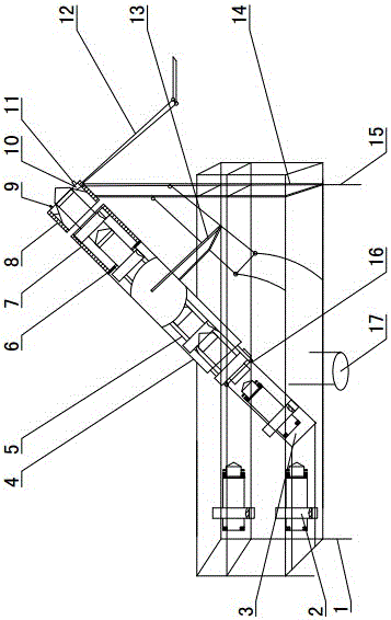
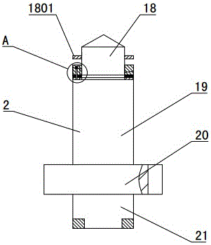
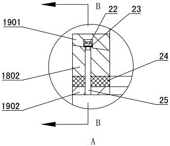
[0038] Such as figure 1 Shown: the mechanical continuous type pneumatic fire extinguishing gun includes a barrel and a fire extinguishing shell 2, and one end of the barrel is rotatably mounted on the frame 1. Frame 1 comprises upper and lower two layers, and the upper layer is used for placing shell and gun barrel, and the lower floor is used for placing shell conveying device and power unit. The gun barrel has a rotating and separating unit that drives the high-pressure launching cylinder 19 and the fire-extinguishing bullet 18 to rotate relatively, so that the high-pressure launching cylinder 19 and the fire-extinguishing bullet 18 are relatively rotated and then the clamping mechanism is separated to realize firing.

[0039] The shell delivery device includes a shell transporter 3 and a guide barrel 4 . The shell carrier 3 is installed on the left side of the frame 1 lower floor, and the outlet end of the guide barrel 4 communicates with the inlet end of the barrel. Fram...

Embodiment 2

[0073] The difference between embodiment 2 and embodiment 1 is that the rotating barrel 7 is coaxially provided with gears, the output shaft of the gearbox is provided with gears, and the motor drives the rotating barrel 7 to rotate through gear transmission. The motor is a servo motor, and the motor is connected with a PLC controller, and the firing speed of the fire-extinguishing shells 2 and the firing interval of two adjacent fire-extinguishing shells 2 are adjusted by the PLC controller.

Embodiment 3

[0075] The difference between embodiment 3 and embodiment 1 is: the guide barrel 4 and the shell transporter 3 are installed on the ground, and when fire extinguishing is required, they are assembled on site, which takes up little space and is convenient for transportation.

[0076] Fire extinguishing materials such as dry powder can also be adorned in the fire-extinguishing warhead 18, and motor can also be speed-regulating motor, and the output shaft of motor is provided with straight pin, is used for driving rotating gun barrel 7 and rotates.


PUM


Abstract

The invention discloses a mechanical continuous pneumatic fire extinguishing cannon, and belongs to the field of fire-protection fire extinguishing equipment. The mechanical continuous pneumatic fire extinguishing cannon is characterized in that a fire extinguishing shell (2) comprises a fire extinguishing shell head (18) and a high-pressure shooting barrel (19), one end of the high-pressure shooting barrel (19) is sealed, the other end of the high-pressure shooting barrel (19) is fixedly connected with the fire extinguishing shell head (18) in a clamped manner through a clamping and fixing mechanism, and the high-pressure shooting barrel (19) is filled with high pressure gas; and the fire extinguishing shell (2) is fixed into a cannon barrel, the cannon barrel is provided with a rotating separating unit for driving the high-pressure shooting barrel (19) and the fire extinguishing shell head (18) to relatively rotate, the clamping and fixing mechanism is separated after the high-pressure shooting barrel (19) and the fire extinguishing shell head (18) relatively rotate, and the high pressure gas in the high-pressure shooting barrel (19) pushes the fire extinguishing shell head (18) to be shot. According to the mechanical continuous pneumatic fire extinguishing cannon, site gas charging is not required, timely shooting can be achieved, and continuous shooting is achieved.

Description

technical field [0001] A mechanical continuous pneumatic fire extinguishing cannon belongs to the field of fire extinguishing equipment, and in particular relates to a pneumatic fire extinguishing cannon capable of continuous firing realized by a mechanical structure. Background technique [0002] With the rapid development of society and the shortage of land resources, more and more real estate developers choose to develop high-rise buildings to cope with the growing demand for housing. Real estate development is in full swing, but the supporting life security system has not been developed accordingly. One of the most prominent is the construction of fire-fighting equipment. It is understood that among the fire brigades in large and medium-sized cities in China, there are very few fire brigades equipped with ultra-high ladders. In some smaller county and city-level units, there is almost no high-level fire fighting equipment. Facing today's buildings with 30 or 40 floors ...

Claims


Application Information

Patent Timeline
IPC IPC(8): A62C31/00A62C31/28
CPCA62C31/00A62C31/28
Inventor 许伟伟张硕李强张学腾马龙张金子
Owner CHINA UNIV OF PETROLEUM (EAST CHINA)
Why Eureka
Try Eureka