Device for cleaning petroleum drilling rod

A technology for oil drill pipes and equipment, which is applied in the field of equipment for cleaning oil drill pipes. It can solve the problems of low manual cleaning efficiency, high operating intensity, and physical hazards for construction workers, achieving high efficiency, reducing work cycles, and increasing Effect of spray range

Inactive Publication Date: 2015-11-11
CHENGDU LAIBAO PETROLEUM EQUIP
View PDF6 Cites 12 Cited by
  • Summary
  • Abstract
  • Description
  • Claims
  • Application Information

AI Technical Summary

Problems solved by technology

[0003] In order to solve the defects of low manual cleaning efficiency, high operating intensity and easy to cause harm to the construction personnel, the present invention provides equipment for cleaning oil drill pipes.

Method used


Image

  • Device for cleaning petroleum drilling rod
  • Device for cleaning petroleum drilling rod

Examples


Embodiment 1

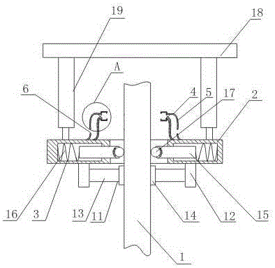
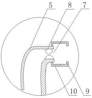
[0020] Such as figure 1 , figure 2 As shown, the equipment for cleaning the oil drill pipe includes an annular rotating plate 2 sleeved on the outer diameter of the oil drilling pipe 1, and the inner wall of the annular rotating plate 2 has a ring cavity; The clamping device 3 in the ring cavity; also includes a spray washing device 4 fixed on the upper surface of the annular rotating plate 2, the spray washing device 4 includes a nozzle body 5 with a cavity structure, and an inlet is opened on one side of the nozzle body 5. There is a water outlet A7 on the other side of the water outlet 6; it also includes a hemisphere 8 evenly arranged on the inner wall of the nozzle body 5 around the water outlet A7, and the hemisphere 8 is made of rubber material; The cover body 9 which is a cavity structure, the water outlet A7 is located in the cavity structure of the cover body 9;

[0021] In this embodiment, the pipeline for transporting the derusting agent is connected to the wate...

Embodiment 2

[0023] On the basis of Embodiment 1, this embodiment also includes a cleaning device 11 arranged on the lower surface of the annular rotating plate 2. The cleaning device 11 includes a connecting block 12, a connecting rod 13 connected with the connecting block 12, and a connecting rod 13 fixed on the connecting rod 13. The grinding body 14 at the end and the side of the connection block 12 are arranged on the annular rotating plate 2 .

[0024] The grinding body 14 in this embodiment can derust the oil drilling pipe 1 when the annular rotating plate 2 moves or rotates up and down along the axis of the oil drilling pipe 1, and the grinding sheet made of quartz stone has a better effect.

Embodiment 3

[0026] In this embodiment, on the basis of Embodiment 1 or Embodiment 2, the clamping device 3 includes a support rod 15 slidably arranged in the ring cavity, and also includes two ends connected to the inner wall of the ring cavity and the rear end of the support rod 15 respectively. The spring 16, the front end of the support rod 15 passes through the opening of the ring cavity and is arranged outside the ring cavity, and a universal ball 17 arranged at the front end of the support rod 15 is also included.

[0027] In this embodiment, when the annular rotating plate 2 is not sleeved on the oil drilling pipe 1, the spring 16 will be in the original state, and when the annular rotating plate 2 is sleeved on the oil drilling pipe 1, the spring 16 will be compressed to support The universal ball 17 at the front end of the rod 15 will squeeze the oil drill pipe 1 . The arrangement of the spring 16 and the universal ball 17 makes the present invention applicable to oil drill pipes...


PUM


Abstract

The invention discloses a device for cleaning a petroleum drilling rod. The device comprises an annular rotating plate. The outer diameter of the petroleum drilling rod is sleeved with the annular rotating plate. An annular cavity is formed in the inner wall of the annular rotating plate. The device further comprises clamping devices evenly arranged in the annular cavity around the center of the annular rotating plate. The device further comprises a spraying device fixed to the upper surface of the annular rotating plate. The spraying device comprises a spraying head body of a cavity structure. A water inlet is formed in one side face of the spraying head body, and a water outlet A is formed in the other side face of the spraying head body. The device further comprises hemispheroids evenly arranged on the inner wall of the spraying head body around the water outlet A. The hemispheroids are made of rubber materials. The device further comprises a cover body of a cavity structure. The cover body is fixed to one end of the spraying head body. The water outlet A is formed inside the cavity structure of the cover body. Horn mouths are evenly formed in the side wall of the cover body. A water outlet B is formed in the front end face of the cover body. Due to the arrangement of the hemispheroids, the pressure of a rust remover flowing through the hemispheroids is increased, and the spraying range of the rust remover can be effectively enlarged.

Description

technical field [0001] The invention relates to a cleaning device, in particular to a device for cleaning oil drill pipes. Background technique [0002] After the oil drill pipe is used, a dirt layer and a rust layer will be formed on the surface. During equipment maintenance, the oil drill pipe needs to remove the dirt layer and rust layer on the surface. Now, the dirt layer and rust layer are generally removed manually by hand-held grinders. However, the manual removal method has a long construction period, high operation intensity and extremely low efficiency. Furthermore, due to the existence of petroleum substances and rust substances on the surface of the used oil drill pipe, during grinding, the high temperature and high-speed rotation effect will easily cause the rust dust to be lifted into the air, causing construction workers to inhale the dust. Contents of the invention [0003] In order to solve the defects of low efficiency of manual cleaning, high operating ...

Claims


Application Information

Patent Timeline
Patent Type & Authority Applications(China)
IPC IPC(8): B08B3/02B24B27/033B05B1/34
CPCB08B3/02B05B1/34B24B27/033
Inventor 谭正怀
Owner CHENGDU LAIBAO PETROLEUM EQUIP
Why Eureka
Try Eureka