

Random marking head without rigid inner core
A marking head and rigid technology, which is applied in the field of random marking heads, can solve the problems of small height difference between the liquid level of the ink tank and the ink outlet, high processing accuracy requirements, small inner core and outer jacket, etc., and achieve low manufacturing difficulty , Good randomness, easy processing and manufacturing
- Summary
- Abstract
- Description
- Claims
- Application Information
AI Technical Summary
Problems solved by technology
Method used
Image

Examples
Embodiment approach 1
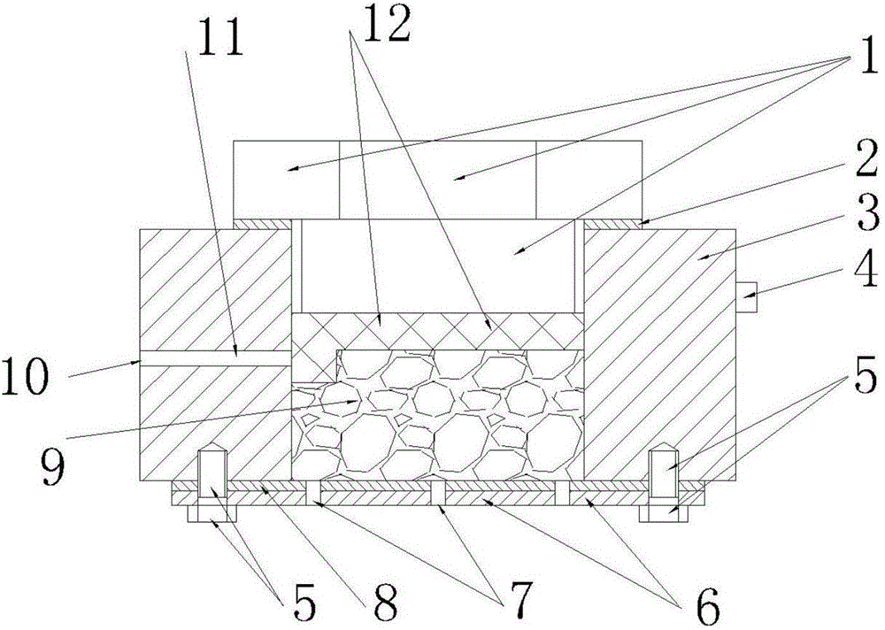
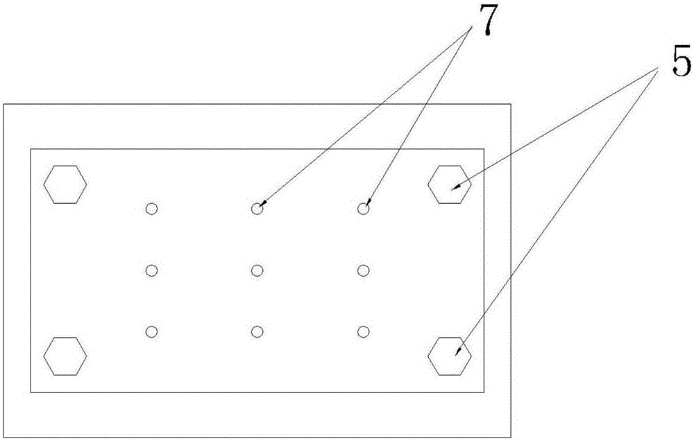
[0038] Such as figure 1 As shown, the planing surface schematic diagram of a random marking head without rigid inner core proposed by the present invention figure 1 , is a schematic diagram of Embodiment 1, including 1. Upper cover, 2. Upper seal, 3. Housing, 4. Connection, 5. Lower cover fixing screw, 6. Lower cover, 7. Ink outlet, 8. Lower seal, 9. Filler, 10. Ink inlet, 11. Ink channel, 12. Shan net.
[0039] The upper cover 1, the upper seal 2 and the housing 3 are installed in cooperation, and the installation and sealing methods are prior art, preferably using the upper cover 1 and the screws provided on the housing 3 to cooperate and install; the connection 4 is used to connect The swing arm can be screwed, welded, etc., which is the prior art, and the preferred welding method is used; the lower cover 6, the lower seal 8, the lower cover fixing screw 5 and the housing 3 are installed in cooperation, which is the prior art; The ink outlet 7 is located on the lower cove...
Embodiment approach 2
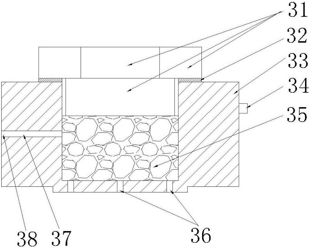
[0066] Such as image 3 As shown, it is a planing schematic diagram of a random marking head without a rigid inner core proposed by the present invention figure 2 , is a schematic diagram of the second embodiment, including an upper cover 31 , an upper seal 32 , a housing 33 , a connection 34 , a filler 35 , an ink outlet 35 , an ink channel 37 , and an ink inlet 38 .
[0067] Compared with the first embodiment, the change of the second embodiment is that the lower cover 6 is gone, and the ink outlet 35 is directly arranged at the lower part of the casing 33 .
[0068] The filler 35 inside the housing 33 is provided in the same manner as in the first embodiment; the gauze 12 is optionally provided in the housing 33 . The installation of the filler 35 is installed through the channel formed after opening the upper cover 31 .
[0069] The installation and connection of other components are the same as in the first embodiment.
Embodiment approach 3
[0071] Such as Figure 4 As shown, it is a planing schematic diagram of a random marking head without a rigid inner core proposed by the present invention image 3 , is a schematic diagram of the third embodiment, including an ink passage 41, a gauze 42, a filler 43, a connection 44, a housing 45, a lower seal 46, a lower cover 47, an ink outlet 48, a lower cover fixing screw 49, and an ink inlet 50.
[0072] Embodiment 3 Compared with Embodiment 1, the change is that the upper cover 1 and the casing 45 are of an integral structure.
[0073] The installation of filler 43 is installed through the channel formed after opening lower cover 47 .
[0074] Such as Figure 4 As shown, the mesh 42 is cake-shaped, and downward protrusions can also be provided on the side facing the ink channel 41 ; grooves can also be arranged on the mesh 42 .
[0075] The gauze 42 provided in the housing 45 is optional; preferably a gauze is provided.
PUM
 Abstract
Description
Claims
Application Information