Electromechanical interlocking control method for safe scram of escalator

An electromechanical interlocking, escalator technology, applied in escalators, transportation and packaging, etc., can solve problems such as personal safety accidents, and achieve the effect of direct and effective safety emergency stop method

Pending Publication Date: 2015-11-11
姜长平
View PDF6 Cites 17 Cited by
  • Summary
  • Abstract
  • Description
  • Claims
  • Application Information

AI Technical Summary

Problems solved by technology

When multiple personal accidents actually occurred, no one was able to operate the emergency stop button in an emergency response, indicating that the operators must be trained before they may operate, thus causing multiple personal safety accidents

Method used


Image

  • Electromechanical interlocking control method for safe scram of escalator
  • Electromechanical interlocking control method for safe scram of escalator
  • Electromechanical interlocking control method for safe scram of escalator

Examples


Embodiment approach 1

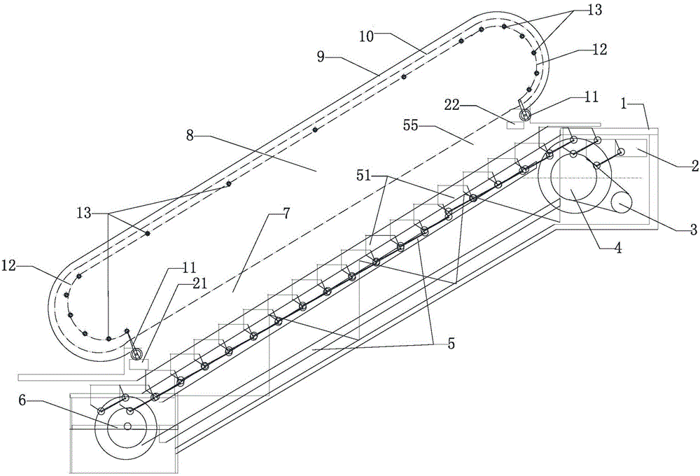
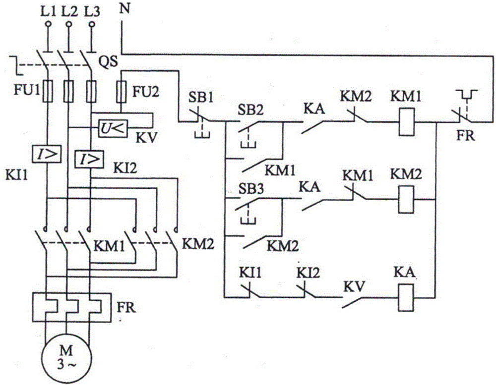
[0021] Embodiment one, electromechanical interlock control method, by figure 1 , 4 Description, it is characterized in that: in the control box 2 of the electric drive system installed on the steel structure truss of the elevator, in the overload protection circuit of the electrical control circuit, a control circuit emergency stop button switch SB1 circuit line is directly connected in series. 11 circuit wires (SB11) of the pull-rope switch, and the SB11 wiring circuit in the pull-rope switch 11 is normally closed, so that the pull-rope switch SB11 and the emergency stop button switch SB1 in the overload protection circuit play an electromechanical double safety protection role, and The original thermal relay FR plays the role of electromechanical multiple safety protection; when the elevator fails, anyone on or around the elevator can pull the pull rope 12 set on the hand support safety plate in time, so that the electric control circuit SB11 circuit of the pull rope switch ...

Embodiment approach 2

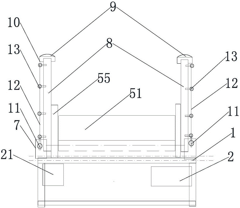
[0022] Embodiment 2, electromechanical interlock control method, by figure 2 , 4 Description, it is characterized in that: the pull rope switch 11 is fixed at the end of the steel structure truss of the elevator, and the control circuit line emergency stop button switch 21 (SB1) in the power control box 2 is connected with the pull rope switch 11. The normally closed circuit line SB11 is connected in series. When an accident occurs, it is not necessary for the personnel on the elevator to squat dangerously or bend over to press the emergency stop button switch 21 arranged on the inner guard plate 55 below the entrance and exit of the escalator. Anyone on the elevator can pull the pull rope 12 at any time to start the pull rope switch 11 to control the circuit SB11 to cut off the fault, so that the KM1 or KM2 normally closed contacts connected in series in the main circuit are disconnected, and the traction motor M running in an emergency stop is realized. The elevator stops ...


PUM


Abstract

The invention provides an electromechanical interlocking control method for safe scram of an escalator. According to the method, an escalator steel structure truss, a mechanical transmission system and an electrical dragging system are involved. The method is characterized in that pull switches are arranged on the head and the tail of the escalator steel structure truss, and by utilizing the electromechanical interlocking characteristic of the pull switches, electrical control circuit wires of the pull switches are directly connected to a control loop of the electrical dragging system in series; mechanical interlocking pull ropes are arranged on supporting plates fixed below operating hand belts of the mechanical transmission system. Compared with the prior art, the electromechanical interlocking control method has the beneficial effects that training is not needed, and the dangerous operation that a person bends over or squats to press a scram button is not needed; when human injuries happen in the operation process of the escalator, any person on the escalator can operate the pull switches for emergency response so as to cut off failures in time to prevent accidents; the electromechanical interlocking control method is brand new, safe and reliable.

Description

technical field [0001] The invention relates to the technical field of fail-safe control of special equipment escalators, in particular to an electromechanical interlock control method for safe emergency stop of escalators. Background technique [0002] Currently, at the top of the escalator in an escalator, an electric motor drives the transmission gear to turn the chain coils. Both the electric motor and the chain system are mounted in the frame, which is the metal structure that runs between the two floors. The steps remain level as the chain moves. At the top and bottom of the escalator, the steps fold over each other to form a platform. This makes getting on and off the escalator easier. Each step on an escalator has two sets of wheels that turn along two separate tracks. The upper unit (the wheel near the top of the steps) is connected to a rotating chain and pulled by a drive gear located at the top of the escalator. The other set of wheels simply slides along th...

Claims


Application Information

Patent Timeline
Patent Type & Authority Applications(China)
IPC IPC(8): B66B25/00B66B29/00
CPCB66B25/00B66B29/00
Inventor 姜长平姜博白晰
Owner 姜长平
Why Eureka
Try Eureka