Manual stirring type magnetizer

A stirring and magnetizer technology, applied in the field of magnetism and magnetization, can solve the problems of complex design, poor effect, inappropriateness, etc., and achieve the effect of saving motor cost, simple and reliable design, and not easy to fail.

Inactive Publication Date: 2015-11-11
NANJING MAGNESTER ENVIRONMENTAL PROTECTION SCI & TECH LTD
View PDF5 Cites 0 Cited by
  • Summary
  • Abstract
  • Description
  • Claims
  • Application Information

AI Technical Summary

Problems solved by technology

[0006] At present, there are many magnetization patents in China, especially the magnetization cup patents are also developed into products, but the results are not good. The main reasons are as follows: 1. The liquid in the container is almost still and cannot produce vertical cutting motion with the magnetic field, so little effect on magnetization
2. The relative movement speed of the liquid and the magnetic field is insufficient or inappropriate
3. Because the temperature is higher than 80 ℃, the general permanent magnet will be demagnetized, so the magnet has to be placed in the interlayer of the cup body, and the inner shell of the cup is used to insulate and lower the temperature. However, when the temperature drops, the magnetic force is insufficient due to the long distance.
4. When the magnet is placed in the interlayer of the cup, only the magnetic force lines facing the inside of the cup can be used, and the magnetic force lines in other directions are wasted, which is not conducive to magnetic shielding
5. There will still be demagnetization after being placed in hot water near 100°C for a long time
6. There is a patent for installing a small motor-driven stirrer in the container, but the motor is damaged due to steam leakage, and energy consumption is required (such as CN00261837 patent)
Seven. The design is too complicated, and the manufacturing cost is too high

Method used


Image

  • Manual stirring type magnetizer
  • Manual stirring type magnetizer
  • Manual stirring type magnetizer

Examples


Embodiment Construction

[0024] The accompanying drawings disclose the specific structures of the embodiments of the present invention without limitation, and the present invention will be further described below in conjunction with the accompanying drawings.

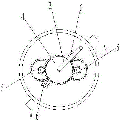
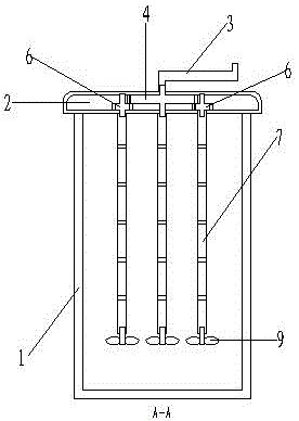
[0025] Such as figure 1 , 2 , 3, the present invention includes a cup-shaped container 1 and a container cover 2, in the container cover 2 is provided with a set of acceleration gears rotated by a hand handle 3, the acceleration gear set is driven by a driving gear 4 and two concentric gears 5 , combined with the internal teeth of the concentric gear 5, the number of teeth of the driving gear 4 is m times that of the internal teeth of the concentric gear 5, and then the external teeth of the concentric gear 5 drive the two driven gears 6 to complete the acceleration action, the concentric gear 5 The number of external teeth is n times that of the driven gear 6. Therefore, when the hand crank 3 rotates one turn, the driven gear 6 rotates m×n ti...


PUM


Abstract

The invention relates to liquid magnetizing equipment for manually driving magnetic pillars to rotate and spirally stir. According to a main device, a group of accelerating gears are arranged in a container cover and are driven by a handshaking handle, and after acceleration, a plurality of vertical magnetic pillars are driven by a rotating shaft; the accelerating gears finish the acceleration in a manner that one driving gear drives two concentric gears to drive two driven gear sets; outer layers of the magnetic pillars are covered with stainless steel, the directions of magnetic lines and the axial directions of the magnetic pillars are accordant and are vertical direction, and liquid can be orthorhombically cut along a peripheral tangent direction during rotation and is therefore magnetized; screw propellers are respectively arranged under the magnetic pillars and can be used for stirring liquid, so that liquid in all directions of a container can be adequately magnetized. The liquid magnetizing equipment is a magnetizer having the advantages that the magnetizing effect is excellent, the structure is simple, energy source is not required, the high temperature of 100 DEG C can be borne, and meanwhile, the container cover together with the magnetic pillars can independently sleeve to or can be independently inserted into a normal cup for use.

Description

technical field [0001] The invention relates to the technical field of magnetism and magnetization, in particular to a manual stirring type liquid magnetization equipment. Background technique [0002] Magnetization technology is generally divided into electromagnetic and permanent magnet, and what the present invention relates to is permanent magnet. [0003] There are two basic conditions for magnetizing a liquid: [0004] Secondly, a certain vertical cutting speed is required, that is, the fluid needs to have a certain relative flow velocity with the magnetic field. It is known from many literatures that this relative velocity has a wide range. The magnetized water used for concrete mixing has an optimal relative flow velocity of about It is 70-80cm / sec. It is used in magnetized water for agricultural irrigation and human drinking. Its relative flow rate is above 40cm / sec. influence, it is difficult to obtain an absolute optimum value. [0005] If the magnetized water ...

Claims


Application Information

Patent Timeline
Patent Type & Authority Applications(China)
IPC IPC(8): C02F1/48
Inventor 高明雄
Owner NANJING MAGNESTER ENVIRONMENTAL PROTECTION SCI & TECH LTD
Why Eureka
Try Eureka