Electroplating equipment

A technology of electroplating equipment and electroplating tank, which is applied in the direction of electrolysis process, electrolysis components, etc., can solve problems such as affecting the quality of the coating layer, and achieve the effects of low input cost, convenient continuous production, and improved wear resistance.

Inactive Publication Date: 2015-11-11
SUZHOU HUARI JINLING MACHINERY
View PDF8 Cites 2 Cited by
  • Summary
  • Abstract
  • Description
  • Claims
  • Application Information

AI Technical Summary

Problems solved by technology

[0004] But existing equipment has following example problem when carrying out electroplating to different workpieces, the one, dispersive ability: the dispersive ability of plating solution refers to the ability that deposit metal is evenly distributed on the cathode part surface under certain electrolytic conditions; Leveling ability: Leveling ability (that is, microscopic dispersion ability) refers to the ability of the plating solution to make the microscopic profile of the coating smoother than the surface of the substrate when the coating is formed on the metal surface. The leveling ability expresses the ability of the substrate metal The roughness is relatively small, the depth of the wave hole is less than 0.5mm, and the uniformity of the coating distribution on the surface with a small distance between the peak and the trough; this phenomenon is especially obvious when electroplating galvanized, cadmium, lead and other metals. When the leveling ability When it is not good, it will appear: pinholes or pitting. The main reason for pinholes or pitting is that hydrogen gas adheres to the surface of the cathode in the form of bubbles, preventing metal from depositing in these parts. It can only be deposited around the bubbles. If The hydrogen bubbles stay on the surface of the cathode during the entire electroplating process, and the plated coating will have holes or through gaps; if the hydrogen bubbles do not adhere firmly during the electroplating process, they escape and adhere alternately intermittently , then these parts will form shallow pits or points, which are usually called pinholes or pits in the electroplating industry; the third is bubbling: after electroplating, when the temperature of the surrounding medium rises, the hydrogen absorbed in the base metal accumulates It will expand and cause small bubbles in the coating, which seriously affects the quality of the coating; the fourth is covering ability: covering ability (or deep plating ability) is also an important performance index of the plating solution, which refers to the deposition of metal under certain electrolytic conditions. The ability to fully cover the surface of the cathode part, that is, the ability to deposit a metal coating in a groove or a deep hole under certain conditions, it refers to the completeness of the distribution of the coating on the part; the fifth is hydrogen embrittlement: after hydrogen ions are reduced at the cathode , part of which forms hydrogen escapes, and part of it penetrates into the base metal (especially high-strength metal materials) and the coating in the state of atomic hydrogen, which reduces the toughness of the base metal and the coating and becomes brittle. This phenomenon is called "hydrogen embrittlement"

Method used


Image

  • Electroplating equipment
  • Electroplating equipment

Examples


Embodiment 1

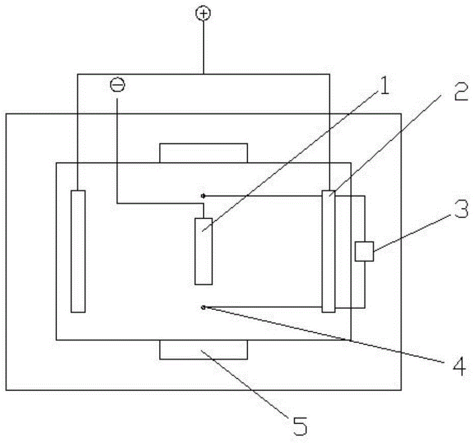
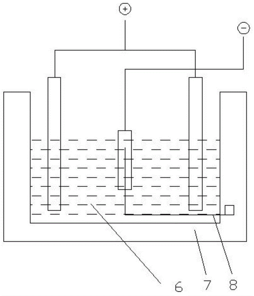
[0024] The electroplating equipment includes an electroplating anode 2, an electroplating cathode 1, an electroplating tank housing 7, and an electroplating solution 6, and also includes a temperature control device and an ultrasonic generator 5. The temperature control device includes a thermometer 4 and a temperature controller 3, and the thermometer 4 is located at On the side of the electroplating cathode 1, the thermostat 3 is located at one end of the electroplating tank housing 7, and the thermometer 4 and the thermostat 3 are connected by a connecting line 8; the ultrasonic generator 5 is located at the side of the electroplating tank housing 7; The outer surface of the connecting wire 8 has an insulating rubber layer.

[0025] The working process of the equipment is that during the electroplating process, the temperature control equipment is used to control and display the temperature of the electroplating solution 6; the ultrasonic generator 5 generates ultrasonic wav...

Embodiment 2

[0027] The electroplating equipment includes an electroplating anode 2, an electroplating cathode 1, an electroplating tank housing 7, and an electroplating solution 6, and also includes a temperature control device and an ultrasonic generator 5. The temperature control device includes a thermometer 4 and a temperature controller 3, and the thermometer 4 is located at On the side of the electroplating cathode 1, the thermostat 3 is located at one end of the electroplating tank housing 7, and the thermometer 4 and the thermostat 3 are connected by a wire 8; the ultrasonic generator 5 is located on the side of the electroplating tank housing 7. The temperature controller 3 and the ultrasonic generator 5 are connected by signals, and the temperature controller 3 controls the operation and stop of the ultrasonic generator 5 through signal transmission.

[0028] The working process of the equipment is that during the electroplating process, the temperature control equipment is used ...

Embodiment 3

[0030] The electroplating equipment includes an electroplating anode 2, an electroplating cathode 1, an electroplating tank housing 7, and an electroplating solution 6, and also includes a temperature control device and an ultrasonic generator 5. The temperature control device includes a thermometer 4 and a temperature controller 3, and the thermometer 4 is located at On the side of the electroplating cathode 1, the thermostat 3 is located at one end of the electroplating tank housing 7, and the thermometer 4 and the thermostat 3 are connected by a connecting line 8; the ultrasonic generator 5 is located at the side of the electroplating tank housing 7; The ultrasonic generating device 5 is set regularly, and the ultrasonic generating device 5 works intermittently.

[0031] The working process of the equipment is that during the electroplating process, the temperature control equipment is used to control and display the temperature of the electroplating solution 6; the ultrason...


PUM


Abstract

The invention belongs to the field of electroplating and particularly relates to electroplating equipment. The electroplating equipment comprises an electroplating anode, an electroplating cathode, an electroplating tank shell, electroplating liquid, a temperature-control device and an ultrasound generation device. The temperature-control device comprises a thermometer and a temperature controller, wherein the thermometer is located on the side surface of the electroplating cathode, the temperature controller is located at one end of the electroplating tank shell, and the thermometer and the temperature controller are connected through a connecting line. The ultrasound generation device is located on a side surface inside the electroplating tank shell. In this way, the electroplating equipment realizes flat and uniform electroplating of the surface of a workpiece, and guarantees that the electroplated workpiece is not likely to be subjected to hydrogen embrittlement.

Description

technical field [0001] The invention belongs to the field of electroplating, in particular to electroplating equipment. Background technique [0002] Electroplating refers to a surface processing method in which in a salt solution containing the metal to be plated, the base metal to be plated is used as the cathode, and through electrolysis, the cations of the metal to be plated in the plating solution are deposited on the surface of the base metal to form a coating. . The performance of the coating is different from that of the base metal and has new characteristics. According to the function of the coating, it is divided into protective coating, decorative coating and other functional coatings. The basic process of electroplating is to immerse the part in a solution of metal salt as the cathode, and the metal plate as the anode, and then deposit the desired coating on the part after connecting to a DC power supply. [0003] At present, there are many electroplating equi...

Claims


Application Information

Patent Timeline
Patent Type & Authority Applications(China)
IPC IPC(8): C25D17/00C25D5/20
Inventor 向延海
Owner SUZHOU HUARI JINLING MACHINERY
Why Eureka
Try Eureka