Check patentability & draft patents in minutes with Patsnap Eureka AI!

Base plate of four-crawler-belt sliding formwork paver

A slip-form paver and four-track technology, which is applied to roads, road repairs, roads, etc., can solve problems such as incompetence, narrow use range, and difficult construction, and achieve the effect of stable operation

Active Publication Date: 2015-11-11
SHANDONG VANSE MECHANICAL TECH CO LTD
View PDF6 Cites 0 Cited by
  • Summary
  • Abstract
  • Description
  • Claims
  • Application Information

AI Technical Summary

Problems solved by technology

This self-propelled sliding form paver usually includes a power system, a walking drive system, a hydraulic actuator system, an automatic control system, etc. The chassis of the sliding form paver is supported on 3-4 crawler belts or tire assemblies. The device unit can be adjusted individually to keep the chassis of the paver on a horizontal plane. This traveling support device unit can also rotate the crawler belt or tires left and right, so that the paver can turn stably and freely when the paver is moving. The paver chassis is equipped with different functions. Equipment units such as: milling device, material conveying device, replacement sliding form adjusting device, sliding form forming mold, vibrating rod or vibrating plate are integrated into one, and the known existing sliding form paver has three crawlers and four crawler self-propelled The four-track self-propelled slip-form paver has a vertically traveling bottom-mounted slip-form die type and a side-mounted slip-form die-type slip-form paver. The two structures are different and their working principles are the same. Both methods are Surrounding pavement paving and paving of road bump guardrails, curbstones, and drainage ditches, the directional function is very prominent, and the use function is single and the scope of use is very narrow. Second, the existing slip-form paver pavement slip-form mold is assembled on the slip-form The two sides of the lower end of the paver chassis are self-propelled on the inner side of the crawler. This method is very difficult to construct in narrow construction conditions, because the crawler belts on both sides of the lower mold of the slipform paver occupy a certain space, and it is difficult to be competent in construction in narrow conditions.

Method used


Image

  • Base plate of four-crawler-belt sliding formwork paver
  • Base plate of four-crawler-belt sliding formwork paver
  • Base plate of four-crawler-belt sliding formwork paver

Examples


Embodiment 1

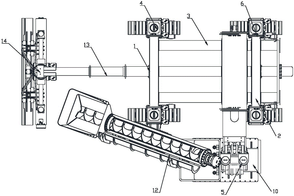
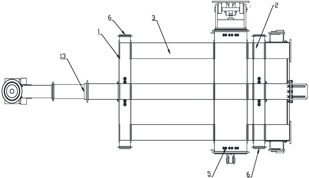
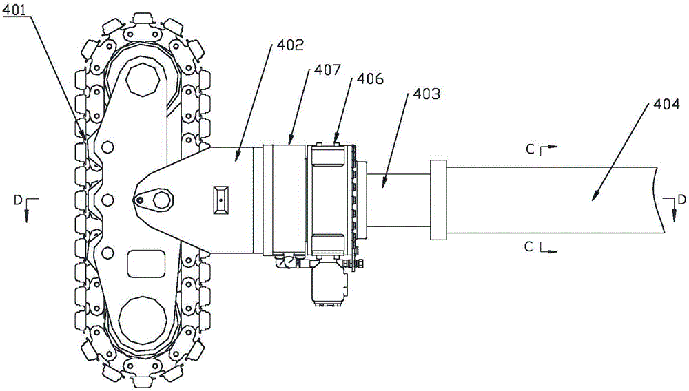
[0035] Such as Figure 1 to Figure 11 As shown in the figure, the chassis of a four-track slipform paver includes a hollow horizontal front beam 1 and a hollow horizontal rear beam 2 arranged side by side in the same horizontal plane. The two ends of the horizontal front beam 1 and the horizontal rear beam 2 respectively pass through the longitudinal beams 3 The two ends of the transverse front beam 1 and the transverse rear beam 2 are respectively connected to the traveling steering device 4, and a leveling head telescopic beam 13 arranged parallel to the longitudinal beam is provided between the two longitudinal beams 3, and the leveling head telescopic beam 13 penetrates Passing the bottom center position of the transverse front beam 1 and the transverse rear beam 2 and perpendicular to the transverse front beam 1 and the transverse rear beam 2, the leveling head telescopic beam 13 is provided with a leveling head 14 at one end close to the transverse front beam 1.

[0036] The...

Embodiment 2

[0041] Such as Figure 3 to Figure 6 and Figure 8 to Figure 15 As shown in the figure, the overall structure of this embodiment 2 is the same as that of embodiment 1, except that the longitudinal beam 3 on the rear side of the transverse rear beam 2 is provided with a mold connection port 7, and the mold connection port 7 is connected to the rear mold 8.

[0042] The rear mold 8 includes a beam frame 801, a rectangular connecting beam 802, a spiral cloth shaft 803, a vibrating rod 804, a wiper plate 805, and a side adjustment plate 806. The beam frame 801 includes a square main beam frame 807, which is fixed above the main beam frame 807 A rectangular connecting beam 802 is provided. The front and rear faces of the rectangular connecting beam 802 are welded with connecting ports 808. The connecting ports 808 are used to connect with the mold connecting port 7. A spiral cloth shaft 803 is fixed at the bottom of the front end of the main beam frame 802. The vibrating rod cylinder 8...

Embodiment 3

[0044] Such as Figure 3 to Figure 11 and Figure 16 to Figure 18 As shown in the figure, the chassis of a four-track slipform paver includes a hollow horizontal front beam 1 and a hollow horizontal rear beam 2 arranged side by side in the same horizontal plane. The two ends of the horizontal front beam 1 and the horizontal rear beam 2 respectively pass through the longitudinal beams 3 The two ends of the transverse front beam 1 and the transverse rear beam 2 are respectively connected to the traveling steering device 4, and a leveling head telescopic beam 13 arranged parallel to the longitudinal beam is provided between the two longitudinal beams 3, and the leveling head telescopic beam 13 penetrates Passing the bottom center position of the transverse front beam 1 and the transverse rear beam 2 and perpendicular to the transverse front beam 1 and the transverse rear beam 2, the leveling head telescopic beam 13 is provided with a leveling head 14 at one end close to the transver...


PUM


Abstract

The invention discloses a base plate of a four-crawler-belt sliding formwork paver. The base plate comprises a hollow front cross beam and a hollow rear cross beam which are arranged on the same horizontal plane in parallel side by side. The two ends of the front cross beam and the two ends of the rear cross beam are integrally fixed and arranged through longitudinal beams. Proceeding steering devices are connected to the two ends of the front cross beam and the rear cross beam respectively, a leveling head telescopic beam parallel to the longitudinal beams is arranged between the two longitudinal beams, penetrates the center position of the bottom of the front cross beam and the center position of the bottom of the rear cross beam and is perpendicular to the front cross beam and the rear cross beam, and a leveling head is arranged at the end, close to the front cross beam, of the leveling head telescopic beam. The base plate has the advantages that operation is stable, flexibility is high, accessories are fast and convenient to replace, the construction efficiency is high, the structure is simple, the production cost is reduced, the purchasing and using performance cost ratio is high, and construction cost is reduced due to the modularized combination mode.

Description

Technical field: [0001] The invention relates to a road engineering equipment, in particular to a chassis of a four-track slipform paver. Background technique: [0002] Slip-mode cement concrete paver (referred to as slip-form paver). It integrates concrete distribution, metering, vibrating, sliding-form extrusion, flat rubbing, and smoothing. It can automatically, high-quality, one-time Pour the concrete material on the roadbed. This kind of self-propelled slipform paver usually includes a power system, a walking drive system, a hydraulic execution system, an automatic control system, etc. The chassis of the slipform paver is supported on 3-4 crawler or tire assemblies. This traveling support The device unit can be lifted and adjusted separately so that the chassis of the paver always maintains a horizontal plane. This traveling support device unit can also make the crawler or tire rotate left and right, and it can turn stably and freely when the paver is traveling. The chassis...

Claims


Application Information

Patent Timeline
Patent Type & Authority Applications(China)
IPC IPC(8): E01C19/48
Inventor 陈建军
Owner SHANDONG VANSE MECHANICAL TECH CO LTD
Features
  • R&D
  • Intellectual Property
  • Life Sciences
  • Materials
  • Tech Scout
  • Unparalleled Data Quality
  • Higher Quality Content
  • 60% Fewer Hallucinations
Learn More