Pile truss combined type bridge-road transition section structure independent of bridge abutment

A transition section and combined technology, applied in the direction of bridges, bridge parts, bridge construction, etc., can solve the problems of inability to radically eliminate settlement differences in transition areas and reduce transition sections, so as to reduce settlement, reduce load pressure, and overcome excessive self-weight. big effect

Active Publication Date: 2015-11-11
CHINA RAILWAY 21TH BUREAU GROUP
View PDF7 Cites 0 Cited by
  • Summary
  • Abstract
  • Description
  • Claims
  • Application Information

AI Technical Summary

Problems solved by technology

[0005] The technical problem to be solved by the present invention is to provide a pile truss combined bridge road transition section structure independent of the abutment; it can greatly reduce the settlement of the transition section and improve the overall stability of the transition section to solve the problem that the existing technology cannot Settlement differences in transitional areas of bridges (or tunnels, culverts)

Method used


Image

  • Pile truss combined type bridge-road transition section structure independent of bridge abutment

Examples


Embodiment Construction

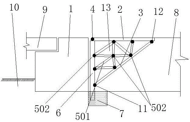
[0015] The present invention will be further described below in conjunction with the drawings. Such as figure 1 Shown: a pile-column-truss combined bridge-road transition section structure independent of abutment, including foundation 10, bridge abutment 1, girder body 9, and road basic body 8, and also includes post-abutment pile 6 and truss transition section structure; The post-abutment pile 6 is fixed behind the abutment 1; the truss transition section structure includes the reinforced concrete prefabricated horizontal slab 2, the reinforced concrete prefabricated diagonal brace slab 3 and the reinforced concrete prefabricated truss member 5; the reinforced concrete prefabricated horizontal slab 2 and the post-abutment pile The upper end of the column 6 is connected by the first high-strength hinged bolt 4, the lower end of the reinforced concrete precast diagonal brace slab 3 and the post-stage pile 6 are connected by the second high-strength hinged bolt 11, and the other ...


PUM


Abstract

A pile truss combined type bridge-road transition section structure independent of a bridge abutment comprises a bridge abutment, a beam body, a roadbed body, a pile behind the bridge abutment, and a truss transition section structure. The pile behind the bridge abutment is disposed behind the bridge abutment. The truss transition section comprises a reinforced concrete horizontal plate, a reinforced concrete diagonal brace plate and a reinforced concrete truss member. The reinforced concrete horizontal plate is connected with the upper end of the pile behind the bridge abutment through hinging bolts, the reinforced concrete diagonal brace plate is connected with the lower end of the pile behind the bridge abutment through hinging bolts, and the other end of the reinforced concrete horizontal plate is connected with the other end of the reinforced concrete diagonal brace plate through hinging bolts. The reinforced concrete horizontal plate, the pile behind the bridge abutment and the reinforced concrete diagonal brace plate form a cavity, and the reinforced concrete truss member is mounted in the cavity. The reinforced concrete diagonal brace plate clings and is fixed to the roadbed body. Problem of settling difference caused by rigidity difference between abnormal structures in traffic lines can be solved by using the structure provided in the invention. The transition section structure between the pile behind the bridge abutment and the truss is suitable for transition between a tunnel culvert and the roadbed, too.

Description

Technical field [0001] The invention relates to the technical field of bridge settlement difference control in traffic engineering, in particular to a pile-column-truss combined bridge-road transition section structure independent of a bridge abutment. Background technique [0002] In the field of traffic engineering, whether it is a road or a railway, the problem of the transition section of the bridge (or tunnel, culvert) is like a stubborn disease that recurs and cannot be completely cured. The "jumping" phenomenon at the bridge head caused by the difference in settlement between the abutment (tunnel or culvert) and the roadbed seriously affects the comfort of driving, reduces the speed of vehicles and the capacity of the road, and at the same time, as the settlement progresses further Increase, increase the damage to vehicles and abutment structures, and bring huge safety hazards to driving safety. [0003] For a traffic line composed of different structures such as bridges, t...

Claims


Application Information

Patent Timeline
Patent Type & Authority Applications(China)
IPC IPC(8): E01D19/00
Inventor 黄志军赵彦旭王晓睫陈向军姚路张杰魏存兰潘亮陈志强夏孝维李玉强
Owner CHINA RAILWAY 21TH BUREAU GROUP
Why Eureka
Try Eureka