Aero-engine labyrinth seal structure with tooth cavity jet

A technology of aero-engine and sealing structure, which is applied in the direction of engine components, machines/engines, mechanical equipment, etc., and can solve problems such as difficult leakage, difficult processing, and limited space for geometric size changes

Inactive Publication Date: 2015-11-11
NANJING UNIV OF AERONAUTICS & ASTRONAUTICS
View PDF6 Cites 14 Cited by
  • Summary
  • Abstract
  • Description
  • Claims
  • Application Information

AI Technical Summary

Problems solved by technology

Due to the small size of the grate tooth seal, its minimum size is less than 1mm, and the processing is more difficult; in addition, the sm

Method used


Image

  • Aero-engine labyrinth seal structure with tooth cavity jet
  • Aero-engine labyrinth seal structure with tooth cavity jet
  • Aero-engine labyrinth seal structure with tooth cavity jet

Examples


Embodiment Construction

[0036] The present invention will be further described below in conjunction with specific examples.

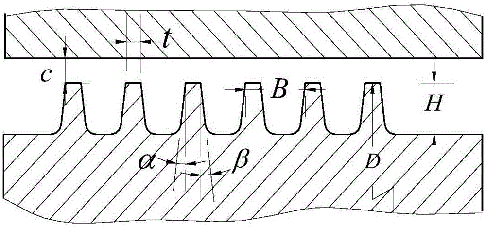
[0037] An aero-engine grate sealing structure with a tooth chamber jet, including a fluid inlet 13, a fluid outlet 14, a sealing bush 11, a rotating shaft 12, and several stages of grate distributed on the rotating shaft. The grate tooth cavity is formed between the grate teeth, and the gap between the teeth is formed between the top of the grate teeth and the top wall of the sealing bush. The sealing bush is installed on the shaft through the structure of the grate teeth; the fluid enters from the fluid inlet, passes When the grate teeth are used, a part of the fluid sticking to the wall jet enters the gap between the teeth of the next stage of the grate teeth to form a tooth tip jet, and the other part of the fluid enters the grate teeth cavity between the two stages of grate teeth to generate a vortex; The bottom wall is provided with radial jet holes in the tooth cavity, t...


PUM


Abstract

The invention relates to an aero-engine labyrinth seal structure with tooth cavity jet. The aero-engine labyrinth seal structure with the tooth cavity jet comprises a fluid inlet, a fluid outlet, a sealing bush, a rotating shaft and multiple levels of labyrinths which are distributed on the rotating shaft, labyrinth tooth cavities are formed between the adjacent two levels of the labyrinths, tooth cavity radial jet holes are formed in the bottoms of the labyrinth tooth cavities and evenly distributed at the bottoms of the cavities between the labyrinths in the circumferential direction, airflow is introduced from the interior of the rotating shaft to form radial jet, fracture of a tooth cavity large vortex structure is facilitated, kinetic energy dissipation of tooth cavity fluid is strengthened, and meanwhile extrusion is formed on tooth tip jet, flow area of the tooth tip jet is reduced, and the leakage rate is controlled. According to the aero-engine labyrinth seal structure with the tooth cavity jet, the tooth cavity jet is adopted, airflow dissipation inside the labyrinths can be effectively enhanced, and the overall leakage flow of the fluid is reduced. The aero-engine labyrinth seal structure with the tooth cavity jet is simple in structure and easy to implement and has good project application value.

Description

technical field [0001] The invention belongs to the field of engines, and in particular relates to an aeroengine grate sealing structure with a tooth cavity jet. Background technique [0002] With the development of the aviation industry, the requirements for the maneuverability, reliability and economy of the aircraft are getting higher and higher, so it is urgent to improve the various components of the aero-engine to ensure the high-performance requirements of the engine. Low fuel consumption, high thrust ratio, high reliability and durability are the development trends of modern aviation gas turbine engines, but the temperature and pressure ratio inside the engine are gradually increasing, making the leakage of the internal flow system more and more serious, and the performance of the seal is directly It affects the performance of aero-engines such as fuel consumption rate, flight cost, and thrust-to-weight ratio. In order to reduce leakage loss and improve the overall ...

Claims


Application Information

Patent Timeline
IPC IPC(8): F02C7/28F01D11/08
Inventor 张勃李经警吉洪湖
Owner NANJING UNIV OF AERONAUTICS & ASTRONAUTICS
Why Eureka
Try Eureka