Vehicle fuel feeding and evaporation system

A fuel supply and evaporation system technology, applied in the direction of charging system, liquid fuel feeder, engine components, etc., can solve problems such as insufficient oil and gas volatilization space, potential safety hazards, carbon tank failure, etc., to facilitate aftermarket modification, management The effect of less road structure changes and prolonging the service life

Inactive Publication Date: 2015-11-11
力帆科技(集团)股份有限公司
View PDF6 Cites 5 Cited by
  • Summary
  • Abstract
  • Description
  • Claims
  • Application Information

AI Technical Summary

Problems solved by technology

If you continue to refill after jumping the gun, the fuel in the fuel tank will be too full, and there will be insufficient space for the volatilization of oil and gas, and even the liquid fuel will directly flow back into the carbon tank, resulting in the failure of the carbon tank, posing a great safety hazard
[0006] 2. The fuel tank is directly connected to the carbon tank through the fuel evaporation pipeline. When the vehicle is not used for a long time or exposed to the sun for a long time, the fuel vapor in the fuel tank will quickly cause the activated carbon in the carbon tank to absorb and saturate until it fails (the engine will not work if the car is not used for a long time. It cannot absorb the fuel vapor from the carbon tank into the engine for combustion)
If the user fails to replace the carbon tank in time, it may also cause liquid fuel to overflow from the carbon tank to the engine room, causing serious safety hazards

Method used


Image

  • Vehicle fuel feeding and evaporation system

Examples


Embodiment Construction

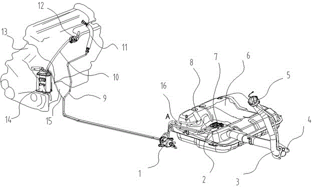
[0018] The present invention will be described in further detail below in conjunction with the accompanying drawings.

[0019] see figure 1 As can be seen from the figure, the vehicle fuel supply and evaporation system of the present invention includes a fuel tank 6, a fuel pump assembly 7, a fuel filter 1, a refueling pipe 3, a refueling vent pipe 4 and a carbon canister 14. The fuel pump assembly 7 is located in the fuel tank 6, the output of the fuel pump assembly 7 is connected to the fuel filter 1 through the fuel outlet pipe assembly 2 of the fuel tank, and the output of the fuel filter 1 is connected to the engine through the oil outlet hard pipe 9 and the engine oil inlet pipe assembly 11 13. There is also a pressure relief return pipeline 8 between the fuel filter 1 and the fuel tank 6 . The fuel tank 6 is connected to the carbon canister 14 through the evaporation pipeline 15, and the output of the carbon canister 14 is connected to the engine 13 through the carbon ...


PUM


Abstract

The invention discloses a vehicle fuel feeding and evaporation system. The vehicle fuel feeding and evaporation system comprises a fuel tank, a fuel pump assembly, a fuel filter, a fuel feeding pipe, a fuel feeding and air ventilating pipe and a carbon tank; and the fuel tank is connected with the carbon tank through an evaporation pipe, and the output of the carbon tank is connected with and engine through a carbon tank absorption pipe. A check valve is arranged on the evaporation pipe for connecting the fuel tank with the carbon tank; and by means of the check valve, the carbon tank and the fuel tank are through in the direction from the carbon tank to the fuel tank, and the carbon tank and the fuel tank are through in the direction from the fuel tank to the carbon tank at a set pressure, wherein the set pressure is larger than the fuel pressure at a fuel feeding opening of the fuel feeding pipe and the lower end of the fuel feeding pipe when fuel feeding pipe is filled with fuel. By means of the vehicle fuel feeding and evaporation system, continuity of fuel injecting after gun closing can be prevented, and the problems that the carbon tank is prone to losing efficiency and the fuel steam is prone to volatizing to the atmosphere due to the fact that liquid fuel in the fuel tank flows into the carbon tank can be solved. The vehicle fuel feeding and evaporation system is low in cost, modifications of an original pope structure are fewer, and convenience is brought to after-market refitting.

Description

technical field [0001] The invention relates to an automobile fuel system, specifically a vehicle fuel supply and evaporation system controlled by a valve system, which is used to prevent excessive fuel filling or liquid fuel in the fuel tank from flowing into the carbon tank through the evaporation pipeline and cause the carbon tank to fail, belonging to the automobile fuel oil system. Supply and fuel evaporation technology field. Background technique [0002] Due to the possibility of fuel evaporation, in order to prevent the fuel in the fuel tank from evaporating into the atmosphere and polluting the air, a carbon canister is installed in the fuel system of the vehicle. The carbon canister is equipped with activated carbon. The carbon canister is connected to the fuel tank through a pipeline, so that the fuel tank produces The steam can enter the carbon tank through the pipeline and be absorbed by the activated carbon. A carbon canister adsorption pipe is arranged betw...

Claims


Application Information

Patent Timeline
IPC IPC(8): F02M37/04F02M25/08
Inventor 王锦龚良才龚中杰
Owner 力帆科技(集团)股份有限公司
Why Eureka
Try Eureka