Improved hydraulic oil tank

A hydraulic oil tank and improved technology, applied in the direction of oil supply tank device, fluid pressure actuation device, fluid pressure actuation system components, etc., can solve the problem of inconvenient disassembly and cleaning, limited ability to filter iron particles, and inability to further ensure hydraulic oil. High quality and other issues

Inactive Publication Date: 2015-11-11
苏州市大力电器有限公司
View PDF5 Cites 15 Cited by
  • Summary
  • Abstract
  • Description
  • Claims
  • Application Information

AI Technical Summary

Problems solved by technology

[0003] However, the above-mentioned filter devices are all installed in the hydraulic oil tank, which is inconvenient to disassemble and clean, and has a limited ability to filter iron particles, which cannot further ensure the high quality of hydraulic oil

Method used


Image

  • Improved hydraulic oil tank

Examples


Embodiment Construction

[0015] The preferred embodiments of the present invention will be described in detail below in conjunction with the accompanying drawings, so that the advantages and features of the present invention can be more easily understood by those skilled in the art, so as to define the protection scope of the present invention more clearly.

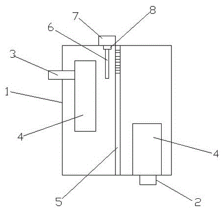
[0016] figure 1 It is a structural schematic diagram of an improved hydraulic oil tank according to the embodiment of the present invention; the hydraulic oil tank includes a tank body 1, an oil suction pipe 2, an oil return pipe 3, a filter assembly 4 and a partition 5, and the filter assembly 4 is installed on the oil suction pipe 2 and the oil return pipe. At the end of the oil pipe 3, the partition plate 5 is vertically installed in the middle of the casing 1, and an electromagnet adsorption device is added on the casing 1. The device mainly consists of a magnetic bar 6, a housing 7, a battery, Switches, control elements and related circuits,...


PUM


Abstract

The invention discloses an improved hydraulic oil tank. The hydraulic oil tank comprises a tank body, an oil suction pipe, an oil return pipe, filter components and a separation plate. The filter components are arranged at the end of the oil suction pipe and the end of the oil return pipe. The separation plate is vertically arranged in the right center of the tank body. An electromagnet attraction device is additionally arranged on the tank body, and is mainly composed of a magnetic rod, a shell, a battery, a switch, a control element and a relevant circuit. The magnetic rod is inserted in the tank body, the battery, the switch, the control element and the relevant circuit are arranged in the shell, and the shell is arranged on the upper portion of the tank body. The improved hydraulic oil tank is reasonable in structural design and unique in function; the electromagnet attraction device additionally arranged on the tank body is convenient to use, mount and clean, manufacturing cost is moderate, and the work state is stable; and a prominent function of attracting scrap iron particles is achieved, the high quality of hydraulic oil can be effectively ensured, and the work stability of a hydraulic system can be improved.

Description

technical field [0001] The invention relates to a hydraulic oil tank, in particular to an improved hydraulic oil tank with the function of efficiently absorbing iron filings particles, and belongs to the technical field of hydraulic accessories. Background technique [0002] The hydraulic oil tank is one of the indispensable components in the hydraulic system. Its main functions are: to store the oil required for the circulation of the system, to dissipate the heat generated when the system works, to release the gas mixed in the oil, and to dissipate heat and separate the oil Foam, impurities, etc. During the operation of the hydraulic system, iron filings particles are inevitably produced, and the iron filings particles are brought into the circulating oil circuit, which will easily accumulate over time and damage the hydraulic components. Therefore, in the existing hydraulic oil tank, filter devices are usually arranged at the nozzles of the oil suction pipe and the oil r...

Claims


Application Information

Patent Timeline
Patent Type & Authority Applications(China)
IPC IPC(8): F15B1/26F15B21/04
CPCF15B1/26F15B21/041
Inventor 陈平
Owner 苏州市大力电器有限公司
Why Eureka
Try Eureka