Gas injection valve with buffer mechanism

A buffer mechanism and gas injection technology, applied in the valve's device for absorbing fluid energy, sliding valve, valve details, etc., can solve the problems of valve life influence, collision, weak buffer effect of injection valve, etc., to reduce collision wear and response. Fast, avoids wear or sticking effects

Active Publication Date: 2015-11-11
WEIFANG LICHUANG ELECTRONICS TECH
View PDF10 Cites 13 Cited by
  • Summary
  • Abstract
  • Description
  • Claims
  • Application Information

AI Technical Summary

Problems solved by technology

[0002] The high-speed electromagnetic gas injection valve with electromagnetic drive can adapt to the smaller flow requirements and lower gas pressure conditions. The Chinese invention patent CN104197027A integral double-valve gas injection valve and its assembly method discloses the gas injection valve proposed by the applicant , which can meet the requirements of large flow and high-speed response, but the valve plate of the valve directly collides with the valve seat, and the life of the valve is affected
[0003] Chinese utility model patent CN204358131U discloses a gas injection valve with a buffer mechanism propo

Method used


Image

  • Gas injection valve with buffer mechanism
  • Gas injection valve with buffer mechanism
  • Gas injection valve with buffer mechanism

Examples


no. 1 example

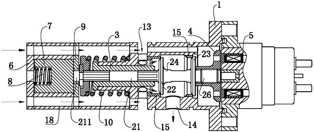
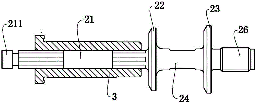
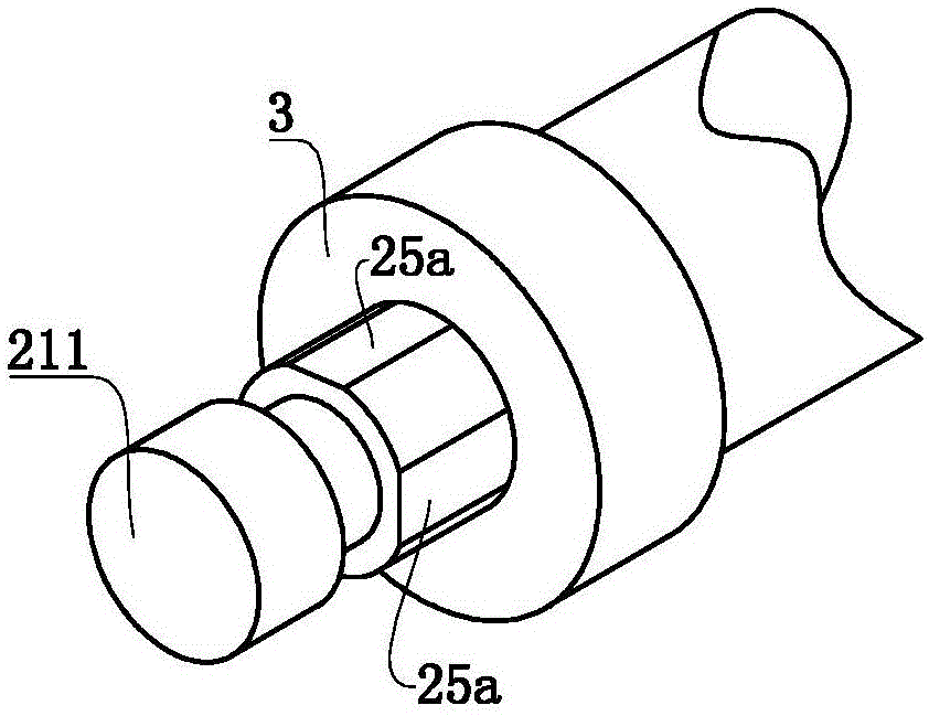
[0027] combine figure 1 and figure 2 Commonly shown, a gas injection valve with a buffer mechanism, the body of the valve body 1 is provided with an air inlet 13 and an air outlet 14, the valve body 1 is provided with a valve seat 15 and a valve core sleeve 3, the valve seat 15 is installed on the valve body 1, or the valve seat 15 is integrated with the valve body 1 (when split manufacturing, the valve seat 15 can be made of more wear-resistant materials), the air inlet 13 and the valve seat Air intake passage is provided between 15. A slidable valve core is installed in the installation hole of the valve core cover 3, and the valve core includes a valve stem portion 21, a valve plate portion and a valve core tail portion 26 arranged in sequence, and the valve plate portion is matched with the valve plate seat 15. For ease of description, the position of the valve stem portion 21 is defined as the “front direction”, and the position of the valve core tail 26 is defined as ...

no. 2 example

[0039] like Figure 4 As shown, its structure is basically the same as that of the first embodiment, the difference is that a groove 25b extending in the axial direction is provided on the peripheral surface of the stem part 21 to replace the notch 25a, and the effect is basically the same.


PUM


Abstract

The invention, which belongs to the technical field of the gas injection valve, especially relates to a gas injection valve with a buffer mechanism. A buffer mechanism is arranged at the front side of a valve body and contains a housing, a front end cover, and a rear end cover; and the housing, the front end cover, and the rear end cover are fixed at the front side of the valve body by fasteners. A through hole is formed in the rear end cover; and a head of a valve rod part passes through the through hole and extends into the housing. A buffer block is arranged inside the housing; and a buffer spring is clamped and compressed between the buffer block and the front end cover. When the gas injection valve is closed, the buffer effect is good; and when the valve is opened, no damping occurs and the response speed is fast.

Description

technical field [0001] The invention belongs to the technical field of gas injection valves, in particular to a gas injection valve with a buffer mechanism. Background technique [0002] The high-speed electromagnetic gas injection valve with electromagnetic drive can adapt to the smaller flow requirements and lower gas pressure conditions. The Chinese invention patent CN104197027A integral double-valve gas injection valve and its assembly method discloses the gas injection valve proposed by the applicant , which can meet the requirements of large flow and high-speed response, but the valve plate of the valve directly collides with the valve seat, and the life of the valve is affected. [0003] Chinese utility model patent CN204358131U discloses a gas injection valve with a buffer mechanism proposed by the applicant. In the later stage of closing of the valve plate of the injection valve, the annular boss of the valve stem is inserted into the buffer groove at the end of the...

Claims


Application Information

Patent Timeline
IPC IPC(8): F16K47/04F16K3/314F16K27/04
CPCF16K3/314F16K27/041F16K47/04
Inventor 王秀强王立峰
Owner WEIFANG LICHUANG ELECTRONICS TECH
Why Eureka
Try Eureka