A double-layer punch

A punching, double-layer technology, applied in the field of parts processing, can solve the problems of not being able to ensure the placement of the workpiece, affecting the qualified rate of the workpiece, stamping deviation, etc., to achieve the effect of simple structure, improving the qualified rate, and buffering the falling speed.

Active Publication Date: 2019-11-12
JIANGSU MINGYU NEW ENERGY RESOURCES
View PDF6 Cites 0 Cited by
  • Summary
  • Abstract
  • Description
  • Claims
  • Application Information

AI Technical Summary

Problems solved by technology

[0004] This kind of double-layer hydraulic punching machine has a simple structure and can better improve work efficiency. When in use, the workpieces can be placed on the working plate 1 and the working plate respectively for stamping work. When stamping batches of workpieces is required, for The placement of workpieces in the stamping process has high requirements. The application text cannot ensure that the same batch of workpieces are placed at the same position on the work plate. At this time, it will cause stamping deviations and affect the pass rate of workpieces.

Method used


Image

  • A double-layer punch
  • A double-layer punch
  • A double-layer punch

Examples


Embodiment 1

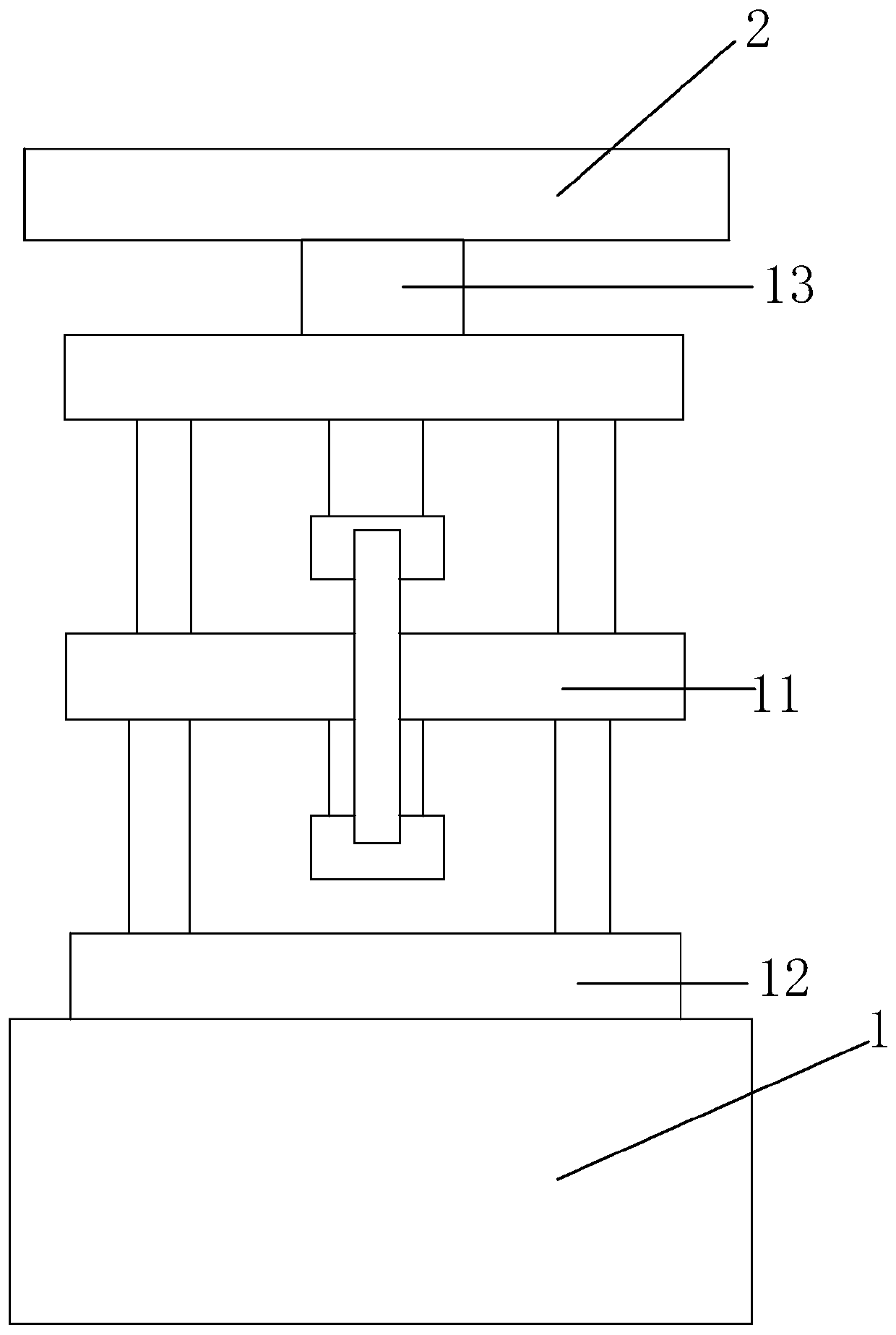
[0029] Embodiment 1: a kind of double-deck punch, such as figure 1 As shown, it mainly includes a frame 1, an upper working plate 11, a lower working plate 12, and a hydraulic cylinder 13 positioned at the top of the frame 1. The hydraulic cylinder 13 is an executive power element, and the workpieces to be processed are respectively placed on the upper working plate 11 and the On the lower working plate 12, and under the action of the hydraulic cylinder 13, two workpieces can be punched simultaneously.

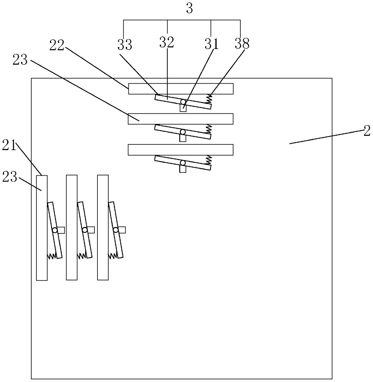
[0030] Such as figure 1 As shown, at this time, a rectangular adjustment plate 2 is fixed horizontally on the top of the hydraulic cylinder 13, as figure 2 As shown, one end of the hydraulic cylinder 13 on the adjustment plate 2 is provided with a plurality of Y-direction limiting channels 21 from the inside to the outside, and the adjustment plate 2 is provided with a plurality of X-direction slots 21 from the inside to the outside on one side of the hydraulic cylinder 13. ...

Embodiment approach

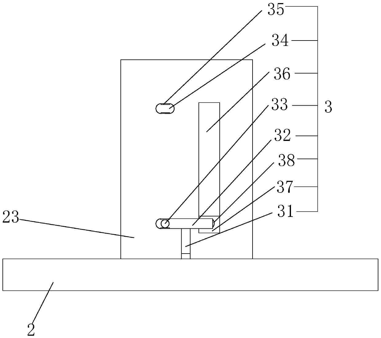
[0032]The specific embodiment: before the workpiece is processed, the positioning plate 23 is all in the non-working state under the effect of the limit mechanism 3, that is, it is all in the place away from the upper working plate 11. At this time, the electromagnet 35 is all in the energized state. The limit rod 33 in the positioning mechanism 3 is inserted into the limit hole at the position of the positioning plate 23 near the bottom, and the connecting spring 38 is in a stretched state; when the workpiece needs to be processed, the workpieces to be processed are respectively placed on On the surface of the upper working plate 11 and the lower working plate 12, and according to the size of the workpiece, select the two positioning plates 23 at the required positions of the Y-direction limiting channel 21 and the X-direction limiting channel 22, and select the positioning of the appropriate position. After the plate 23, the electromagnet 35 at this position is controlled to ...

Embodiment 2

[0036] Embodiment 2: a kind of double-deck punching machine, the difference with embodiment 1 is, as Figure 6 As shown, at this moment, on the adjustment plate 2, a plurality of buffer mechanisms 4 for controlling the falling speed of the positioning plate 23 are provided. The side wall of the positioning plate 23 near the fixed block 41 and located at the upper end position are fixedly provided with a connecting block 42, the bottom surface of the connecting block 42 is fixedly provided with a fixed sleeve 44, and the sliding inside the fixed sleeve 44 is provided with a telescopic rod 45 The upper surface of the fixed block 41 is fixedly provided with a buffer spring, and the end of the buffer spring away from the fixed block 41 is connected and fixed with the lower surface of the fixed sleeve 44, and the outer circumferential surface of the connecting rod 32 conflicts with the inner ring of the buffer spring.


PUM


Abstract

The invention discloses a double-layer punching machine. The double-layer punching machine comprises a rack, an upper working plate, a lower working plate and a hydraulic cylinder located at the top of the rack, wherein an adjustment plate is fixedly arranged at the top of the hydraulic cylinder; a plurality of Y-directional limit through grooves are formed in the adjustment plate and at one end of the hydraulic cylinder in the form of an array; a plurality of X-directional limit through grooves are formed in the adjustment plate and at one side of the hydraulic cylinder in the form of an array; location plates slidably penetrate in the Y-directional limit through grooves and the X-directional limit through grooves separately; working through grooves allowing the location plates to penetrate through are formed in the upper working plate; and a plurality of limit mechanisms controlling the positions of the location plates to be fixed are arranged on the adjustment plate. The double-layer punching machine is capable of realizing simultaneous punching working for two workpieces, and capable of rapidly realizing the uniform positions of the two workpieces on the double-layer punching machine, thereby ensuring the punching qualification rate and increasing the working efficiency.

Description

technical field [0001] The invention relates to the field of parts processing, in particular to a double-layer punch. Background technique [0002] A punch press is a stamping press. In national production, the stamping process has the advantages of saving materials and energy, high efficiency, low technical requirements for operators, and the ability to produce products that cannot be achieved by mechanical processing through various mold applications. Its use is more and more extensive; stamping production is mainly for plates, through the mold, can make blanking, punching, forming, deep drawing, trimming, fine blanking, shaping, riveting and extrusion parts, etc., widely used In various fields, in order to improve processing efficiency, double-layer punching machines came into being. [0003] For example, a double-layer hydraulic punch press (application number: 2015206849619) disclosed on the patent application website includes a frame, a hydraulic cylinder, a working ...

Claims


Application Information

Patent Timeline
Patent Type & Authority Patents(China)
IPC IPC(8): B21D22/02B21D43/00B08B5/02
Inventor 许婷玉
Owner JIANGSU MINGYU NEW ENERGY RESOURCES
Why Eureka
Try Eureka