[0040] Embodiment one
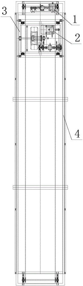
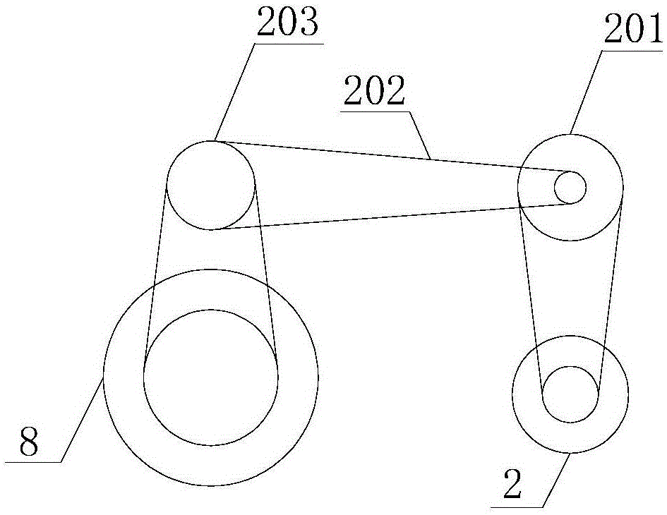
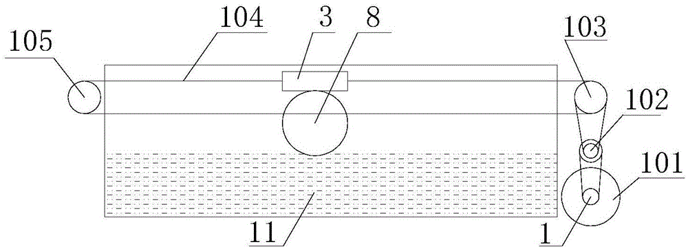
[0041] The single-wheel soil tank test bench of the present embodiment has a structure such as figure 1 , Figure 11 , Figure 12 , Figure 13 and Figure 14 As shown, it includes a soil tank system, a drive system, a drag system, a control system and a data acquisition system, wherein the soil tank system is mainly composed of a soil tank body 5 and a walking guide rail 4 arranged along the soil tank body 5, and the soil tank body 5 is Rectangular box structure, which is equipped with test soil 11, the size requirements of the box structure are as follows: its length should be determined as 9 meters according to the requirements of data collection in the stability test stage, the width should be determined as 1.5 meters according to the requirements of the drive system, and the depth should be 1.5 meters. Determined to be 0.8 meters, which can reduce the impact of soil boundary effects on the test. A first truss is arranged laterally in the box structure. The first truss includes two parallel beams 25, two longitudinal beams 26 and four first columns 27. The beams 25 and the longitudinal beams 26 are connected end to end to form a closed frame. The four corners of the frame are provided with vertically downward first columns 27, and two longitudinal beams 26 are also connected between the two first columns 27 at one end of the frame, and at least Two reinforcing ribs 18. The left and right ends of the first truss are respectively connected to the left and right second trusses. Both the left and right second trusses are composed of three layers of rectangular frames, and each layer of rectangular frames is fixedly connected to the first column 27 on one side of the first truss. , the other side is fixedly connected with the second column, and each floor of the rectangular frame is mainly composed of two side beams 28 oppositely arranged and a sub-beam 29 connecting the ends of the two side beams 28, the sub-beam 29 and the longitudinal beam 26 are arranged in parallel, the side beam 28 is fixedly connected end to end with the sub-beam 29 and the longitudinal beam 26, and the second pillar 30 is vertically arranged at the junction of the side beam 28 and the sub-beam 29. The first truss is connected to the walking guide rail 4 through the guide rail fixing seat 401. The walking guide rail 4 is composed of the first and second channel steels 21. The first channel steel 21 is installed on one of the first trusses through the fixing seat with the opening facing inward. On the crossbeam 25, the second channel steel 21 is installed on another crossbeam 25 of the first truss with the opening facing inward through the fixing seat. In addition, the top floors of the left and right second trusses are provided with a first grid-shaped member, and the first grid-shaped member of the left second truss is equipped with a second reduction gear 105 through a bearing seat 16, and the second reduction gear 105 of the right second truss The first reduction gear 102 and the second driving gear 103 are installed on the first grid-shaped member through the bearing seat 16, and the middle layer of the second right truss is provided with the second grid-shaped member, and the second grid-shaped member is installed on the second grid-shaped member. There is a motor support, and the dragging motor 1 is installed on the motor support.
[0042] The structure of the drive system is as figure 2 and Figure 4 As shown, it includes a drive bracket 3 that is installed on the walking guide rail 4 and moves along the walking guide rail 4. The driving bracket 3 is a rectangular frame, and its four corners are provided with rollers 20. The sides of the rectangular frame pass through a group of double card wheel devices. Cooperate and connect with the opening of the first channel steel or the second channel steel 21, the double card wheel device includes two card wheels 24 up and down, and one end of the card wheel 24 extends outwards from the card wheel support, and the circumferential surface of the card wheel support is in line with the The opening inner walls of the first and second channel steels 21 coincide, the other end of the card wheel 24 is provided with a card wheel shaft 22, and the card wheel shaft 22 is rotatably connected in the shaft hole of the card wheel shaft support 23, and the card wheel shaft support 23 is fixedly installed On the side of the drive bracket 3 (see Image 6 ). In addition, a vertical displacement sensor 14 is arranged outside the frame of the rectangular frame, and the probe of the vertical displacement sensor 14 faces the base plate 10 of the drive system, and four linear bearings 19 are arranged on the frame inside of the rectangular frame, and each linear bearing 19 is provided with Vertical guide rod 7 is arranged, and vertical guide rod 7 can slide up and down along linear bearing 19, and the lower ends of four vertical guide rods 7 are all fixedly installed on the base plate 10 by vertical guide rod support 302, and base plate 10 is shaped on groove, and The base plate 10 is positioned at both sides of the groove to be provided with wheel fixed shaft support 304, and wheel fixed shaft support 304 is equipped with wheel fixed shaft 303, and wheel fixed shaft 303 can rotate in wheel fixed shaft support 304, and wheel fixed shaft 303 It is fixedly connected with the wheel 8 arranged in the groove of the bottom plate 10. The wheel 8 is composed of a wheel hub 803 installed on the wheel fixed shaft 303, a wheel rim 801 fixed outside the wheel hub 803 and a tire 802 sleeved on the wheel rim 801. The wheel hub 803 adopts Universal design, only need to install the flange plate of corresponding tire 802 on the right side of wheel hub 803 during the test, it is convenient to replace different tires 802 for testing. The second reduction sprocket 203 is socketed on the wheel fixed shaft 303, the second reduction sprocket 203 is connected with the second driving sprocket 205 by the transmission chain 202, the second driving sprocket 205 is connected with the first reduction sprocket 201, the first The reduction sprocket 201 is connected with the first driving sprocket 204 installed on the output shaft of the driving motor 2 through the transmission chain 202, and the drive is set between the first reduction sprocket 201 and the second driving sprocket 205 through a coupling 17. Torque-speed sensor 9 (that is, the driving torque-speed sensor 9 is arranged between the first reduction sprocket 201 and the second driving sprocket 205, located in the middle of the torque transmission process, and can accurately measure the transmitted torque and speed value). The power transmission of the drive system is as image 3 As shown, the driving force is sent from the drive motor 2 (YVF132M-4-7.5KW motor from Nanjing Zhongke, with a rated voltage of 380V, a rated power of 7.5KW, and a rated torque of 47.7N·m), and passes through the two stages of the reduction gear. The deceleration is transmitted to the wheels 8 to drive the wheels 8 to rotate, thereby simulating the running of the wheels 8 of the off-road vehicle on soft ground.
[0043] On the bottom plate 10, three counterweight rod supports 301 are evenly arranged on both sides of the wheel 8, and a counterweight bar is installed in the counterweight bar support 301. The upper end of the counterweight bar is provided with a counterweight mounting plate 305 with a triangular cross-section. The counterweight mounting plate 305 is provided with a counterweight 306 for simulating different load test environments.
[0044] drag and drop system such as Figure 5 As shown, the dragging motor 1 is included, the output shaft of the dragging motor 1 is equipped with a first driving gear 101 and a dragging torque-speed sensor 6, the first driving gear 101 is connected with the first reduction gear 102 through a dragging chain 104, The first reduction gear 102 is connected with the second driving gear 103 through the dragging chain 104 , and the second driving gear 103 is connected with the second reduction gear 105 through the dragging chain 104 and the driving bracket 3 . The power transmission of the drag system has two directions, such as image 3 As shown, when the dragging motor 1 (YVF100L-4-3KW motor from Nanjing Zhongke, rated voltage 380V, rated power 3KW, rated torque 19.0N·m) provides rightward dragging force (resistance) , the drag force is transmitted to the drive bracket 3 through the first reduction gear 102 and the second driving gear 103, and then acts on the wheel 8 through the vertical guide rod 7 and the bottom plate 10 to provide rightward resistance for the wheel 8 and limit the direction of the wheel 8. Left movement; when the drag motor 1 provides the drag force to the left, the drag force is transmitted to the drive bracket 3 through the first reduction gear 102, the second driving gear 103 and the second reduction gear 105, and then through the vertical guide rod 7 1. The bottom plate 10 acts on the wheel 8 to provide resistance to the left for the wheel 8 and limit the movement of the wheel 8 to the right, thereby simulating the traction resistance of the wheel 8 during driving.
[0045] In addition, the reduction sprocket/gear and the driving sprocket/gear are all fixedly installed through the bearing seat 16, and the drive motor 2/drag motor 1 is also fixedly installed through the motor support, and the bearing seat 16 and the motor support are provided with adjusting bolts 15. The adjusting bolt 15 is used to adjust the tightness of the transmission chain 202 or the dragging chain 104 to ensure stable torque transmission.
[0046]The control system includes an external computer and a control cabinet installed on the side panels of the soil tank body 5. The control cabinet includes a chassis, a control circuit installed in the chassis and a control panel installed on the outer surface of the chassis. The control panel is divided into three parts: the main control area, the drive control area and the drag control area. The main control area controls the operation of the entire test bench, including the start button, emergency stop button, reset button, drag motor voltage display and drive motor voltage. The display screen, in which the start button is the main switch of the entire control system. When it is displayed as start, other buttons can be operated. The emergency stop button is a safety button for controlling the driving motor 2 and the dragging motor 1. When a fault or When it is necessary to stop, press the emergency stop button to realize the stop of the two motors, so that the control system has an emergency braking function to ensure safety. The reset button can control the operation of the driving motor 2 and the dragging motor 1, so that the driving system returns to the initial position. The drag control area mainly controls the operation of the drag motor 1, including the start button 1, the stop button 1, the forward button 1, the back button 1, the speed control knob 1 and the speed display screen, and the start button 1 controls the circuit of the drag motor 1. When the stop button is pressed, the dragging motor 1 is controlled to stop. When the forward button is pressed, the dragging motor 1 is rotated forward. After being pressed, the drive bracket 3 can be driven to move to the right. When the back button is pressed, the dragging motor 1 is reversed. Afterwards, the driving bracket 3 can be driven to move to the left, and the speed regulating knob 1 is a knob for controlling the speed of the dragging motor 1, and only when one of the forward button 1 or the backward button 1 is turned on, the speed regulating knob 1 can be executed, and the speed display screen It shows the current speed. The drive control area mainly controls the operation of the drive motor 2, including the start button 2, the stop button 2, the forward button 2, the back button 2, the speed control knob 2 and the speed display screen, the start button 2 controls the circuit of the drive motor 2, and the stop button 2 After being pressed, the driving motor 2 is controlled to stop, and the forward button 2 controls the driving motor 2 to rotate forward. After being pressed, the driving bracket 3 can be driven to move to the right. The backward button 2 is controlled to reverse the driving motor 2. After being pressed, the driving bracket 3 can be driven Move to the left, the speed control knob 2 is the knob to control the speed of the drive motor 2, and only when one of the forward button 2 or the back button 2 is turned on, the speed control knob 2 can be executed, and the rotation display screen shows the current speed of the drive motor 2. speed (see Figure 7 ).
[0047] control circuit such as Figure 8 and Figure 9 As shown, it includes a drive control circuit, a drag control circuit and a switch control circuit. The input end of the switch control circuit is connected to the contact of the button switch, and the output end of the switch control circuit is connected to the input end of the drive control circuit or the drag control circuit. . The drive control circuit includes the first relay, the first frequency converter (A100-7.5KW) and the drive motor 2, wherein the control coil of the first relay is connected to the output port of the switch control circuit, and its normally open contact is connected to the start of the first frequency converter The signal input terminal, the output terminal of the first inverter controls the driving motor 2; the drag control circuit includes the second relay, the second inverter (A100-3.7KW) and the drag motor 1, wherein the control coil of the second relay is connected to the switch The output port of the control circuit, its normally open contact is connected to the start signal input end of the second frequency converter, and the output end of the second frequency converter controls the dragging motor 1 . In this way, the button switch controls the frequency converter installed on the motor through the corresponding control circuit and the relay, and then realizes the forward and reverse control of the motor. In addition, the drive motor 2 of the drive control circuit and the drag motor 1 of the drag control circuit are connected to the emergency stop devices respectively installed at both ends of the travel guide rail 4. The emergency stop devices include a travel switch and a travel switch dial matched with the travel switch. The travel switch is installed on the first channel steel or the second channel steel 21 of the walking guide rail 4 at a distance of 260.5±0.1m from the longitudinal beam, and the travel switch dial is installed on the drive bracket 3. When the travel switch toggle block on the drive bracket 3 is in contact with the travel switch, the drive control circuit and the drag control circuit are in a cut-off state, the drive motor 2 and the drag motor 1 stop or reverse, and when the travel switch on the drive bracket 3 When the toggle block is separated from the travel switch, the drive control circuit and the drag control circuit are in the connected state, and the drive motor 2 and the drag motor 1 operate normally. This design can cut off the drag and drive circuit in time, reducing the harm caused by misoperation.
[0048] like Figure 10 As shown, the data acquisition system includes a driving torque-speed sensor 9, a drag torque-speed sensor 6, a vertical displacement sensor 14 and a pressure sensor group 13, a driving torque-speed sensor 9, a drag torque-speed sensor 6, a vertical displacement sensor 14 or the signal output port of the pressure sensor group 13 is connected to the data acquisition card, and the data acquisition card is pluggably connected to the input interface of the external computer, so as to realize accurate collection, convenient storage, display and processing of experimental data. Wherein the pressure sensor group 13 is made of 12 identical dynamic pressure sensors, installed in the inside of the soil tank body 5 . The driving (drag) torque-speed sensor includes a dynamic torque sensor and a speed sensor. The dynamic torque sensor is different from the static torque sensor. It uses the strain gauge electrical measurement technology to form a strain bridge on the elastic shaft, and then provides power to the strain bridge for measurement. Obtain the electrical signal of the torsion of the elastic shaft, then amplify the strain signal, and through the voltage/frequency conversion, it becomes a frequency signal proportional to the torsional strain. In the system, the dynamic torque sensor can be used to measure the dragging motor 1 and drive The driving torque of the motor 2, the rotation speed sensor is used to measure the rotation speed and driving speed of the wheel 8, and the pressure and displacement sensors are used to measure the surface pressure distribution and subsidence respectively. Computer built-in data acquisition and storage related software - LabView software, Labview software (LaboratoryVirtualinstrumentEngineeringWorkbench) is a graphical programming language development environment, it is widely accepted by industry, academia and research laboratories, and is regarded as a standard Data acquisition and instrument control software. Use Labview software to write data acquisition program, which can effectively store and display experimental data.
[0049] When testing the passability of the off-road vehicle, the control system controls the driving motor 2 to work, and provides sufficient driving force for the driving system under the action of the driving motor 2, and the driving force drives the wheel 8 to rotate, thereby driving the bottom plate 10 in the test soil 11 Moving forward, the bottom plate 10 transmits the driving force to the driving bracket 3 through the vertical guide rod 7, and the driving bracket 3 rolls in the guide rail to realize the function of simulating the linear motion of the wheel 8. While the driving bracket 3 is rolling, the control system controls the dragging motor 1 to work to provide sufficient pulling force for the driving bracket 3, and the dragging motor 1 applies a reaction force to the driving bracket 3 through the dragging chain 104 linked on the driving bracket 3, and then The process of simulating the slipping of the wheel 8, the driving direction and speed of the wheel 8 are variable during the test, and the change of the slipping rate of the wheel 8 can be simulated in the range of 0-100%. The slip rate of the wheel 8 is an important factor affecting the dynamic performance of the vehicle, and the driving torque, the sag of the wheel 8, and the traction force of the hook are all related to the slip rate, so obtaining the mechanical parameters under various slip rates is the key to the vehicle performance test . While the driving system and the dragging system are working, the vertical displacement sensor 14, the pressure sensor group 13, the driving torque transmission-wheel speed sensor and the dragging torque-speed sensor 6 collect the data passing the performance test in real time, and pass the data through data acquisition. The card is sent back to the computer, stored and displayed by the computer's Labview software, and provides basic data for verifying the established wheel-ground coupling model. In addition, during the test, the water content of the soil was controlled by sprinkling water on the test soil 11. After measuring the soil parameters, the stress distribution of the soil and the basic parameters of the subsidence coupling model can be known according to the formula. Therefore, obtaining these parameters is very important for verifying the model and even further modifying the model. very important.