Microwave fence radar apparatus and target detection method

A radar device and fence technology, which is applied to measurement devices, radio wave measurement systems, and radio wave reflection/re-radiation, etc., can solve problems such as inability to distinguish the direction of target movement, degradation of radar system performance, and loss of signal power.

Active Publication Date: 2015-11-11
UNIV OF ELECTRONICS SCI & TECH OF CHINA
View PDF4 Cites 21 Cited by
  • Summary
  • Abstract
  • Description
  • Claims
  • Application Information

AI Technical Summary

Problems solved by technology

[0006] The purpose of the present invention is to provide a microwave fence radar device and a target detection method to solve the problems of signal power loss and the inability to distinguish the direction of target movement when detecting long-distance fast intrusion targets, which leads to the degradation of radar system performance

Method used


Image

  • Microwave fence radar apparatus and target detection method
  • Microwave fence radar apparatus and target detection method
  • Microwave fence radar apparatus and target detection method

Examples


Embodiment 1

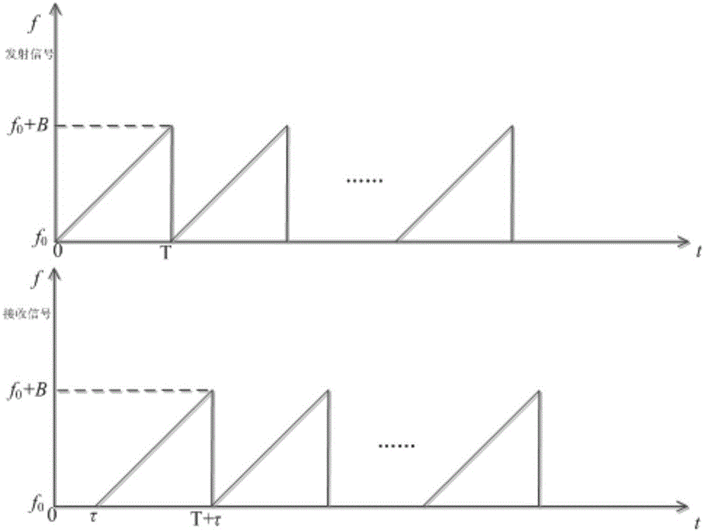
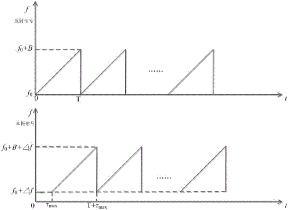
[0103] Such as Figure 4 As shown, the microwave barrier radar device described in this embodiment includes a clock manager, a signal transceiver unit, a digital signal processor, a controller, and an alarm information output interface, and the clock manager is a signal transceiver unit, a digital signal processor, and a controller Provide the clock, the signal transceiver unit is used to generate the transmission signal and local oscillator signal, and process the signal, the processed signal is input to the digital signal processor, the controller reads the processed result of the digital signal processor, and according to the processing As a result, it is judged whether to instruct the alarm information output interface to output alarm information. Such as image 3 Shown is a schematic diagram of the transmit signal and the local oscillator signal.

[0104]Specifically, the signal transceiving unit includes a transmitting part and a receiving part. The transmitting part i...

Embodiment 2

[0187] The airport surveillance system adopts the microwave fence radar to prevent illegal targets from intruding. The delay of the signal realizes the function of the existing perimeter detection radar. This example starts from the requirements of airport surveillance to verify the effectiveness of the present invention in preventing illegal personnel from intruding in the field of airport surveillance.

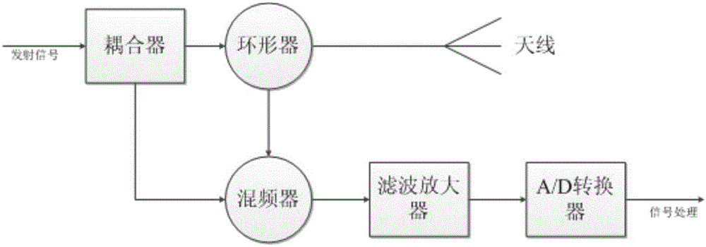
[0188] Here, based on the dual-antenna structure described in Embodiment 1, this example provides another implementation structure of the microwave fence radar device, as shown in the attached Figure 11 As shown, the figure is relative to the attached Figure 4 , combining the receiving and transmitting antennas into one, and replacing them with a circulator Figure 4 in the receiving antenna.

[0189] When transmitting, the controller writes the frequency control word to the transmitting signal generator to generate the required LFMCW signal, and the generated LFMCW sign...


PUM


Abstract

The invention discloses a microwave fence radar apparatus and a target detection method. The microwave fence radar apparatus comprises a clock manager, an signal transmit-receive unit, a digital signal processor, a controller and an alarm information output interface. The clock manager provides a clock for the signal transmit-receive unit, the digital signal processor and the controller. The signal transmit-receive unit is used for generating an emission signal and a local-oscillator signal and processing the signals. The processed signals are input into the digital signal processor. The controller reads a result obtained through processing of the digital signal processor and determines whether to indicate the alarm information output interface to output alarm information according to the processing result. By using the apparatus and the method of the invention, false-alarm to a system, which is generated because a fence is far away from a target, can be avoided. Compared to an existing boundary detection technology, by using the apparatus and the method of the invention, when long-distance rapid invasion target detection is performed, system detection performance is increased.

Description

technical field [0001] The invention relates to the field of radar detection, in particular to a microwave fence radar device and a target detection method. Background technique [0002] Perimeter detection means that when important facilities are connected to the external environment, an isolation measure is added to prevent the intrusion of all unauthorized people and animals. With the development of society, people's demand for all-weather and all-weather perimeter detection is increasingly strong, which makes microwave fence radar emerge as the times require, and is widely used in many occasions such as anti-terrorism, island reef defense, and airport surveillance. [0003] Due to the advantages of FMCW radar over pulse radar in the field of perimeter detection [ButlerW.BenefitsofwideareaintrusiondetectionsystemusingFMCWradar], most existing microwave fence radars use FMCW signal system. CarusoM et al. of the University of Rome developed an X-band FMCW airport surveilla...

Claims


Application Information

Patent Timeline
Patent Type & Authority Applications(China)
IPC IPC(8): G01S13/88G01S13/34
CPCG01S13/34G01S13/88
Inventor 陈祝明洪惠宇张新旺
Owner UNIV OF ELECTRONICS SCI & TECH OF CHINA
Why Eureka
Try Eureka