Compressed-sensing-based entangled light imaging device and imaging method against background of strong interference

A technology of compressed sensing and imaging methods, applied in optics, optical components, instruments, etc., can solve problems such as instability, deviation of coincidence counting, and performance degradation of imaging results, and achieve the effect of simplifying design

Active Publication Date: 2015-11-11
XIDIAN UNIV
View PDF2 Cites 18 Cited by
  • Summary
  • Abstract
  • Description
  • Claims
  • Application Information

AI Technical Summary

Problems solved by technology

[0005] In the literature "Entangled-photoncompressiveghostimaging", PetrosZerom et al. propose to use entangled photon pairs generated by parametric down-conversion as a light source, and obtain the imaging results of the original signal according to the coincidence counts generated by the light source and the random pattern reconstruction of the spatial light modulator (SLM) , and can effectively reduce the number of measurements required to reconstruct random patterns; in addition, under the premise of a given reconstruction quantum ghost imaging mean square error, the number of entangled photon pairs required by compressed sensing is much smaller than that required by scanning methods number; in summary, this method not only reduces the time required to obtain the imaging results of the original signal, but also is more economical; lead to biased coincidence counts, and can also cause performance degradation or instability in imaging results

Method used


Image

  • Compressed-sensing-based entangled light imaging device and imaging method against background of strong interference
  • Compressed-sensing-based entangled light imaging device and imaging method against background of strong interference
  • Compressed-sensing-based entangled light imaging device and imaging method against background of strong interference

Examples


Embodiment Construction

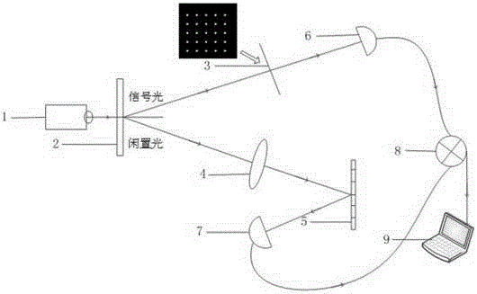
[0039] refer to figure 1 , is a schematic diagram of an entangled optical imaging device based on compressed sensing under a strong interference background of the present invention, which is characterized in that it includes: a laser 1, a BBO crystal 2, an object to be imaged 3, a lens 4, and a spatial light modulator (SLM) 5 , a first single photon detector 6, a second single photon detector 7, a coincidence counter 8, and a data processing module 9;

[0040] The laser 1 generates laser light; the laser center frequency generated by the laser 1 is 457nm, the pulse duration is 5ns, the repetition frequency is 10HZ, and the maximum output power is 300mw;

[0041] The BBO crystal 2 performs spontaneous parametric down-conversion with the laser to obtain entangled light, the entangled light is composed of signal light and idle light, and then the signal light is sent to the target 3 to be imaged, and the idle light is sent to the lens 4; the BBO crystal 2 is a type II phase-matc...


PUM


Abstract

The invention discloses a compressed-sensing-based entangled light imaging method against the background of strong interference. According to the technical scheme, a laser 1 generates laser; spontaneous parametric down conversion is carried out on the laser by a BBO crystal 2 to obtain signal light and idle light; the signal light passes through a to-be-imaged object 3 and a first single-photon detector 6 successively to obtain signal light passing through the first single-photon detector 6; a lens 4 collects the idle light to obtained collected idle light and sends the collected idle light to a spatial light modulator5; the spatial light modulator 5 carries out amplitude modulation on the collected idle light and then the modulated light passes through a second single-photon detector7; the light is sent to a coincidence counter 8; the coincidence counter 8 records coincidence counting of the signal light passing through the first single-photon detector 6 and the idle light passing through the second single-photon detector7 to obtain a measurement matrix and a coincidence counting column vector; and a data processing module 9 obtains an imaging result of the to-be-imaged object 3 based on the measurement matrix and the coincidence counting column vector.

Description

technical field [0001] The invention belongs to the technical field of quantum radar, in particular to an entangled light imaging device and imaging method based on compressed sensing in a strong interference background, which is suitable for quantum imaging in a strong interference background. Background technique [0002] Quantum imaging is a new type of imaging technology developed by using the phenomenon of quantum entanglement. It can also be called two-photon correlation imaging, intensity correlation imaging and ghost imaging. As a new imaging technology, quantum imaging, that is, the realization of entangled light source ghost imaging in ghost imaging, can make it possible to transmit object image information in one of the two independent spaces; thermal light sources can also achieve intensity correlation Imaging, that is, quantum imaging. Compared with classical imaging, quantum imaging has the following advantages: 1) Super-resolution imaging of quantum imaging—t...

Claims


Application Information

Patent Timeline
Patent Type & Authority Applications(China)
IPC IPC(8): G02B27/00G02B27/10
CPCG02B27/00G02B27/10G02B2207/114
Inventor 李军王渊赵启勇廖桂生李晓敏冉艳伟马玉芳郑煜
Owner XIDIAN UNIV
Why Eureka
Try Eureka