

Control device of multiple-antenna system
A multi-antenna system and antenna control technology, which is applied in the field of communication, can solve the problems of large sending and receiving signal angles, long distances, large angles, and small sending and receiving signal angles.
- Summary
- Abstract
- Description
- Claims
- Application Information
AI Technical Summary
Problems solved by technology
Method used
Image

Examples
Embodiment 1
[0029] Hereby, the technical content and detailed description of the present invention are described as follows in conjunction with the drawings:
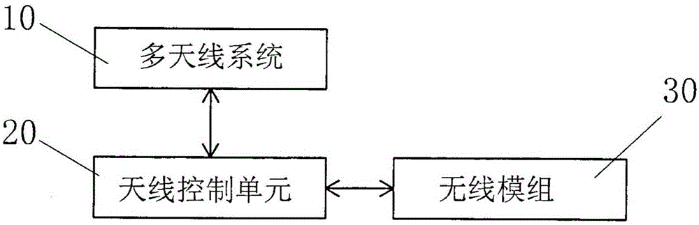
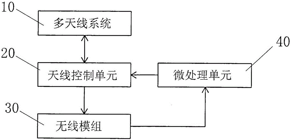
[0030] see figure 2 , figure 2 It is a circuit block diagram of the control device of the multi-antenna system according to the first embodiment of the present invention. Such as figure 2 As shown; the control device of the multi-antenna system of the present invention includes: a multi-antenna system 10 , an antenna control unit 20 , a wireless module 30 and a micro-processing unit 40 .
[0031] The aforementioned multi-antenna system 10 is electrically connected with an electronic communication device (not shown in the figure) and with an antenna control unit 20 (electrical connection refers to an electrical performance connection, also called an electrical connection, the same below), for receiving or transmitting wireless RF signal, and transmit the received radio frequency signal (RF) to the antenna control unit 20 . Th...
Embodiment 2
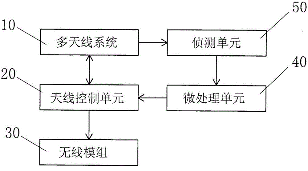
[0039] see image 3 , image 3 It is a circuit block diagram of the control device of the multi-antenna system according to the second embodiment of the present invention, and this embodiment is the same as the above-mentioned figure 2 substantially the same, the difference is that a detection unit 50 is electrically connected between the multi-antenna system 10 and the micro-processing unit 40, and the wireless module 30 is not electrically connected with the micro-processing unit 40, while the wireless module 30 does not need to indicate the received signal strength to the micro-processing unit 40 either.
[0040] The aforementioned detection unit 50 can be installed on a circuit board (not shown in the figure) inside the electronic communication device, and is connected with the multi-antenna system 10 and the micro-processing unit 40 to receive the radio frequency received by the multi-antenna system 10 signal, and calculate the signal strength, and then transmit the ca...
PUM
 Abstract
Description
Claims
Application Information