Strong magnetic coupling and magnetic saturation switch-type fault current limiter and control method thereof

A fault current, strong magnetic coupling technology, applied in the direction of emergency protection circuit devices, electrical components, circuit devices for limiting overcurrent/overvoltage, etc. , material instability and other problems, to achieve the effect of simple and easy control method, suppression of fault current, simple and compact structure

Inactive Publication Date: 2015-11-11
STATE GRID CORP OF CHINA +4
View PDF4 Cites 2 Cited by
  • Summary
  • Abstract
  • Description
  • Claims
  • Application Information

AI Technical Summary

Problems solved by technology

The superconducting fault current limiter has fast response speed and low loss, but the disadvantage is that the cooling system is expensive and the material is unstable; the solid-state limiter is based on a fully controlled device, which has fast limiting and segmentation capabilities, but it is expensive and has a large loss; blasting fault limiter The cost of the device is low, but the maintenance amount is large

Method used


Image

  • Strong magnetic coupling and magnetic saturation switch-type fault current limiter and control method thereof
  • Strong magnetic coupling and magnetic saturation switch-type fault current limiter and control method thereof
  • Strong magnetic coupling and magnetic saturation switch-type fault current limiter and control method thereof

Examples


Embodiment 1

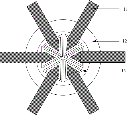
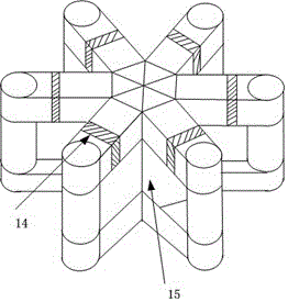
[0023] Embodiment 1 is a three-phase strong magnetic coupling magnetic saturation switch type fault current limiter. Such as figure 1 , figure 2 As shown, the three-phase strong magnetic coupling magnetic saturation switch-type fault current limiter includes a fault current limiter body 15 , six AC coils 13 and one DC coil 12 . The fault current limiter body 15 is mainly composed of six adjacent square-shaped iron cores 11, and the adjacent sides of the six square-shaped iron cores 11 are combined to form a combined middle column, so that the six square-shaped iron cores are surrounded by a whole. The 360°circumferential structure formed by combining the middle columns, in which every two square-shaped iron cores are arranged at 180°, and every two square-shaped iron cores arranged at 180° constitute a phase.

[0024] There is an air gap on the upper yoke of each zigzag iron core. Of course, an air gap can also be selected on the lower yoke or side column, but the position ...

Embodiment 2

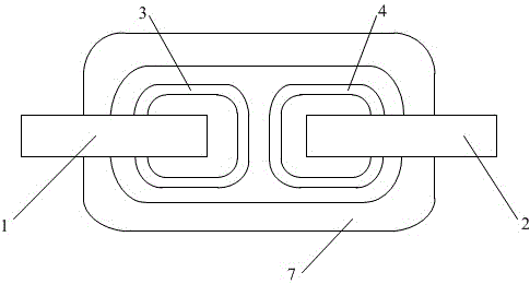
[0028] Such as image 3 , Figure 4 As shown, Embodiment 2 is a single-phase strong magnetic coupling magnetic saturation switch-type fault current limiter, including adjacent first zigzag iron cores 1 and second zigzag iron cores 2 arranged at 180 degrees, the first AC coil 3 , second AC coil 4 and DC coil 7 . Adjacent sides of the first zigzag iron core 1 and the second zigzag iron core 2 are combined to form a combined intermediate column, so that the first zigzag iron core 1 and the second zigzag iron core 2 form the fault current limiter body.

[0029] Air gaps 5 and 6 are respectively arranged on the side columns of the first zigzag iron core 1 and the second zigzag iron core 2. Of course, air gaps can also be selected on the lower yoke or the upper yoke, but each zigzag iron core The position of the air gap setting on the core should be the same. At the same time, the sizes of the air gaps 5 and 6 should be the same, so that the first zigzag iron core 1 and the secon...


PUM


Abstract

The invention discloses a strong magnetic coupling and magnetic saturation switch-type fault current limiter and a control method thereof, and belongs to the technical field of electrician. The strong magnetic coupling and magnetic saturation switch-type fault current limiter is divided into a single-phase structure and a three phase structure, and comprises a plurality of hollow-square-shaped iron cores, a direct current coil and alternating current coils, wherein the adjacent edges of the hollow-square-shaped iron cores are combined together to form a combined middle column; the alternating current coils are respectively wound on the adjacent edges of the hollow-square-shaped iron cores; the inphase alternating current coils are connected to a power grid in serial after being connected through dotted terminals; the direct current coil is wound at the outside of the alternating current coils, and can be connected with an adjustable field power supply; an air gap is formed on each hollow-square-shaped iron core; and the adjustable field power supply can be controlled during the control process, so that the fault current limiter can respectively show low impedance and high impedance under a non-fault running status and a fault running status of an electrical power system. The strong magnetic coupling and magnetic saturation switch-type fault current limiter is simple and compact in structure, and is easy to realize, and is high in reliability.

Description

technical field [0001] The invention belongs to the technical field of electric engineering, and more precisely, the invention relates to a magnetic circuit control type fault current limiter suitable for short circuit protection of electric power system and a control method thereof. Background technique [0002] In the context of my country's continuous economic growth, the scale of my country's power system has increased rapidly, and the development of the power system has shown a trend of gradually increasing installed capacity and gradually expanding the scope of interconnection. With the rapid increase of power system transmission capacity, the network structure of power grid interconnection is becoming more and more complex, and the level of short-circuit current in power grids at all levels is increasing, especially the short-circuit current level of the three major load centers in my country, Jingjintang, Yangtze River Delta, and Pearl River Delta. The short-circuit c...

Claims


Application Information

Patent Timeline
Patent Type & Authority Applications(China)
IPC IPC(8): H02H9/02
Inventor 隗华荣武迪蒋应伟侯凯郑建勇姚磊梅军钱滢锋赵晔
Owner STATE GRID CORP OF CHINA
Why Eureka
Try Eureka