Method for controlling parallel power generation system

A technology of a power generation system and control method, applied in the direction of parallel feeding arrangement of a single network, can solve the problems of poor reliability and incapable of redundancy in the system, and achieve the effects of improving reliability, flexible capacity expansion, and easy to achieve current sharing.

Active Publication Date: 2015-11-11
INST OF ELECTRICAL ENG CHINESE ACAD OF SCI
View PDF3 Cites 6 Cited by
  • Summary
  • Abstract
  • Description
  • Claims
  • Application Information

AI Technical Summary

Problems solved by technology

[0006] The purpose of the present invention is to overcome the disadvantages of poor reliability and system redundancy in the prior art, and propose a new control method for parallel power generation systems

Method used


Image

  • Method for controlling parallel power generation system
  • Method for controlling parallel power generation system
  • Method for controlling parallel power generation system

Examples


Embodiment Construction

[0021] The present invention will be further described below in conjunction with the accompanying drawings and specific embodiments.

[0022] The present invention will be described below by taking the control of a DC / DC parallel power generation system as an example.

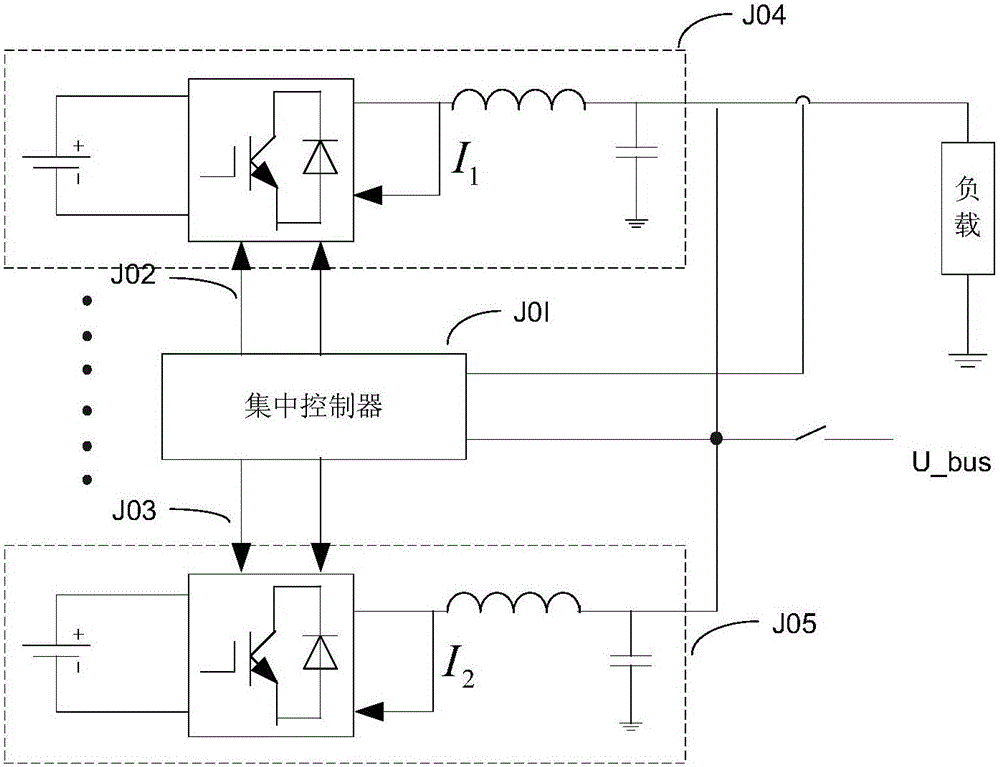
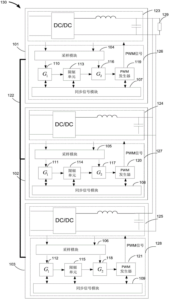
[0023] figure 2 It is the operating system diagram of the parallel power generation system of the present invention, the parallel power generation system 130 is composed of three modules 101, 102, 103, and each module is a DC / DC power generation system. The output voltage reference values ​​of the three modules 101, 102, 103 are respectively U dc1 * , U dc2 * , U dc3 * , and U dc1 * dc2 * dc3 *. The present invention automatically sets the module 101 with the lowest output voltage reference value as the main module through the program, and the modules 102 and 103 as the slave modules. The present invention adopts the double-closed-loop control mode of the voltage outer loop and the current inner lo...


PUM


Abstract

The invention discloses a method for controlling a parallel power generation system. The controlling method comprises the steps that: an amplitude limiting unit is added to a control channel on the double closed-loop foundation of a traditional voltage outer loop and a current inner loop; output values of a voltage regulator are processed via the amplitude limiting unit into output current set values; amplitude limiting values of a slave-module amplitude limiting unit are dynamically adjusted; when a main module normally operates, the amplitude limiting values of the slave-module amplitude limiting unit are equal to the output values of the main module amplitude limiting unit; the output current set values of the main module and the slave module remain the same to realize the synchronous operation of the main module and the slave module and to reach the current-sharing control. When the main module is broken down, a module having the lowest output current reference value is confirmed into the main module to realize the main-slave switch.

Description

technical field [0001] The invention relates to a control method of a parallel power generation system. Background technique [0002] With the development of technology, the power of the power supply system is increasing. In the face of current stress, thermal stress and the selection of expensive high-power power switching devices, the traditional single power supply can no longer meet the requirements. In order to meet the reliability, efficiency and power density requirements of the electrical system, multiple power generation systems are usually used to generate electricity in parallel. The parallel power generation system is generally composed of multiple modules with the same configuration in parallel. Each module is composed of a power circuit and a control circuit. The power circuit is also called the main circuit and is used to transmit the power of the power system. The control circuit is used to control the main circuit. The modules are combined only at the load,...

Claims


Application Information

Patent Timeline
Patent Type & Authority Applications(China)
IPC IPC(8): H02J3/38
Inventor 赵峰王海波温旭辉
Owner INST OF ELECTRICAL ENG CHINESE ACAD OF SCI
Why Eureka
Try Eureka