Large-scale MIMO linear detection hardware framework under non-ideal communication channel, and detection method

A linear detection, large-scale technology, applied in the field of computer communication, can solve the problem that it is impossible to guarantee the ideality of the channel

Active Publication Date: 2015-11-11
SOUTHEAST UNIV
View PDF1 Cites 14 Cited by
  • Summary
  • Abstract
  • Description
  • Claims
  • Application Information

AI Technical Summary

Problems solved by technology

But in our real life, it is impossible to guarantee the ideality of the channel

Method used


Image

  • Large-scale MIMO linear detection hardware framework under non-ideal communication channel, and detection method
  • Large-scale MIMO linear detection hardware framework under non-ideal communication channel, and detection method
  • Large-scale MIMO linear detection hardware framework under non-ideal communication channel, and detection method

Examples


Embodiment Construction

[0035] In this embodiment, a MIMO channel model is established for simulation operation, and the Kronecker model is adopted. According to the Kronecker model, the channel response matrix H of the uplink in the massive MIMO system is written as follows:

[0036] H=R 1 / 2 T

[0037] where R 1 / 2 It is represented by the receiver correlation coefficient matrix. The transmission matrix T is modeled as independent fast fading (fastfading), geometric attenuation (geometricattenuation) and log-normal shadow fading (log-normal shadowfading) coefficient matrices.

[0038] The formula of the correlation coefficient matrix R is as follows:

[0039] R ( c , v ) = ( ζe jθ ) ...


PUM


Abstract

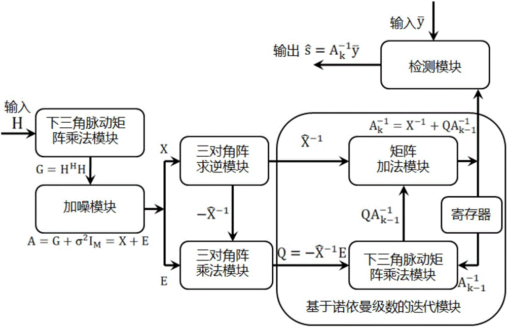
The invention discloses a large-scale MIMO linear detection hardware framework under a non-ideal communication channel. A channel response matrix is enabled to sequentially pass through a triangular pulsation multiplication module and a noise addition module, and enters into a three-diagonal inversion module and a three-diagonal multiplication module. The three-diagonal inversion module selects three-diagonal elements in a matrix outputted by the noise addition module to form a three-diagonal matrix, and carries out the inversion calculation of the three-diagonal matrix. The triangular pulsation multiplication module enables the matrix, which is outputted by the noise addition module, after three diagonals are removed to multiply with a three-diagonal inversion matrix obtained from the three-diagonal inversion module. The results of the three-diagonal inversion module are inputted to a three-diagonal addition module, and the results of the three-diagonal multiplication module are inputted to a lower triangular pulsation multiplication module. The three-diagonal addition module and the lower triangular pulsation multiplication module enable a generated matrix to be inputted to a detection module after loop iteration. The framework reduces the hardware complexity, greatly reduces the calculation complexity, and greatly reduces the throughput rate.

Description

technical field [0001] The invention belongs to the field of computer communication. In particular, it relates to a massive MIMO linear detection hardware framework and a detection method in a non-ideal channel. Background technique [0002] MIMO (Multiple-Input Multiple-Output) technology refers to using multiple transmitting antennas and receiving antennas at the transmitting end and receiving end respectively, so that signals are transmitted and received through multiple antennas at the transmitting end and receiving end. In the current spectrum shortage, it does not start from the frequency, and at the same time, it does not bring greater consumption to the transmission power of the antenna. This technology makes use of space resources, doubles the system channel capacity, improves the communication quality, and has quite superior performance. , is regarded as the core technology of the next generation of mobile communication. Has been included in the fourth generation...

Claims


Application Information

Patent Timeline
Patent Type & Authority Applications(China)
IPC IPC(8): H04B7/04
CPCH04B7/0452H04B7/0456
Inventor 张川梁霄王丰杨俊梅尤肖虎
Owner SOUTHEAST UNIV
Why Eureka
Try Eureka