Two-gear micro ploughing machine

A micro-tiller and engine technology, which is applied in the fields of tillage implements, agricultural machinery and implements, applications, etc., can solve the problems of unfavorable miniaturization, high production cost, large size of the whole machine, etc., and achieves simple structure, low cost, and complete machine. simple structure

Inactive Publication Date: 2015-11-18
CHONGQING JIAMU MACHINERY
View PDF6 Cites 6 Cited by
  • Summary
  • Abstract
  • Description
  • Claims
  • Application Information

AI Technical Summary

Problems solved by technology

[0003] At present, all functional components on the micro tillage machine are arranged around the frame, which not only has complex structure, difficult assembly, high production cost, but also the large size of the whole machine, which is not conducive to the development of miniaturization
In addition, w

Method used


Image

  • Two-gear micro ploughing machine
  • Two-gear micro ploughing machine

Examples


Embodiment Construction

[0016] Below in conjunction with accompanying drawing and embodiment the present invention will be further described:

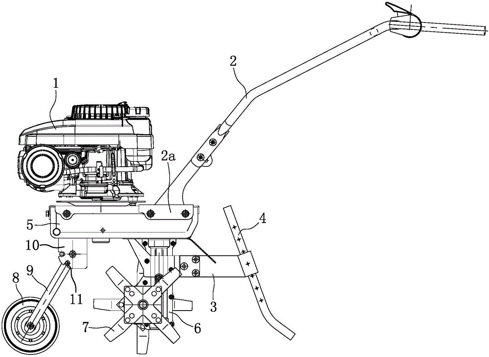
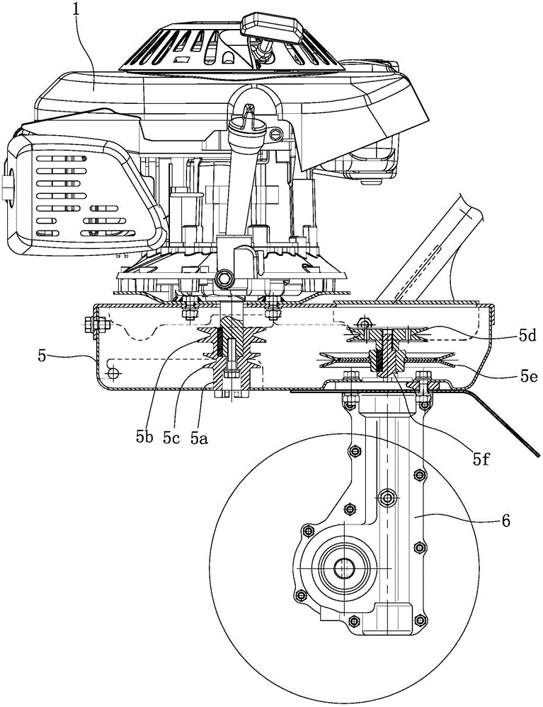
[0017] Such as figure 1 , figure 2 As shown, engine 1 is installed at the front end of main transmission case 5 top, and this engine 1 is the vertical axis engine that output shaft is vertically downward, and the output shaft of engine 1 stretches in the main transmission case 5, and is connected with driving wheel shaft 5a, A high-speed driving wheel 5b and a low-speed driving wheel 5c are integrally formed on the driving wheel shaft 5a, and the high-speed driving wheel 5b is located above the low-speed driving wheel 5c. The high-speed driving wheel 5b can be connected with the high-speed driven wheel 5d through a belt, and the low-speed driving wheel 5c can be connected with the low-speed driven wheel 5e through a belt. Both the high-speed driven wheel 5d and the low-speed driven wheel 5e are arranged on the driven wheel shaft 5f, and the lower end of th...


PUM


Abstract

The invention discloses a two-gear micro ploughing machine. An engine (1) is mounted at the front end of the top of a main transmission case (5), a handhold assembly (2) is mounted at the rear end of the top of the main transmission case (5), an output shaft of the engine (1) extends into the main transmission case (5) and is connected with a driving wheel shaft (5a), the lower end of a driven wheel shaft (5f) is connected with the input end of a worm transmission case (6), and a ploughing knife (7) or a travelling wheel is mounted on an output shaft of the worm transmission case (6); a positioning frame (10) is arranged in front of the worm transmission case (6) and consists of a top plate and side plates symmetrically arranged left and right, the upper end of a sloped tube (9) is positioned between the two side plates of the positioning frame (10), and a front wheel (8) is mounted under the sloped tube (9). The micro ploughing machine disclosed by the invention is simple and compact in structure, small in size and low in cost; the front wheel has two states of folding and unfolding, so that the requirements for different using states of the micro ploughing machine can be met. The micro ploughing machine has two gears of high speed and low speed, and is smooth and reliable in transmission, and the applicable range is wide.

Description

technical field [0001] The invention belongs to the technical field of agricultural machinery, and in particular relates to a two-speed tiller. Background technique [0002] Tillers are powered by small diesel engines or gasoline engines, and have the characteristics of light weight, small size, and simple structure. Tillers are widely used in dry land, paddy fields, orchards, etc. in plains, mountains, and hills. Equipped with corresponding equipment, it can be used for pumping, power generation, spraying, spraying and other operations, and can also be towed for short-distance transportation. The tiller can be used freely in the field, which is convenient for users to use and store, eliminating the need for large-scale agricultural machinery to enter The troubles of mountainous fields are the best choice for the majority of farmers to replace cattle plowing. [0003] At present, all the functional components on the tiller are arranged around the frame, which is not only c...

Claims


Application Information

Patent Timeline
IPC IPC(8): A01B33/02A01B33/10
Inventor 邵海波
Owner CHONGQING JIAMU MACHINERY
Why Eureka
Try Eureka