Integrated hot end structure of pulse tube refrigerator and implementation method

An integrated technology of pulse tube refrigerator, applied in the field of integrated hot end structure of pulse tube refrigerator, can solve the problems of gas flow loss and large weight, complex structure of the whole machine, and numerous pipelines of pulse tube refrigerator, etc. Achieve the effects of improving the integration of the whole machine, simplifying the structure of the whole machine, and reducing the weight of the whole machine

Pending Publication Date: 2021-07-09
SHANGHAI INST OF TECHNICAL PHYSICS - CHINESE ACAD OF SCI
View PDF0 Cites 0 Cited by
  • Summary
  • Abstract
  • Description
  • Claims
  • Application Information

AI Technical Summary

Problems solved by technology

The pulse tube refrigerator is composed of a driving mechanism, a connecting pipe of the driving mechanism, a hot-end heat exchanger, a regenerator, a cold-end heat exchanger, a pulse tube, a regulating connection pipe, and a phase-modulating mechanism. Heaters are arranged separately and are generally connected by gas pipelines, resulting in a large number of pipelines in the commonly used pulse tube refrigerators at present, complex structure of the whole machine, large gas flow loss and weight, and large vacancies in related technologies

Method used


Image

  • Integrated hot end structure of pulse tube refrigerator and implementation method
  • Integrated hot end structure of pulse tube refrigerator and implementation method
  • Integrated hot end structure of pulse tube refrigerator and implementation method

Examples


Embodiment Construction

[0019] The present invention will be described in detail below in conjunction with the accompanying drawings and specific embodiments.

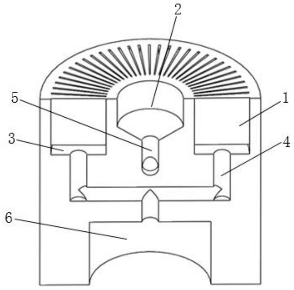
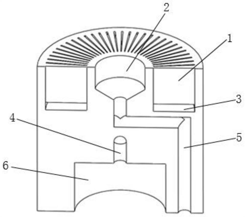
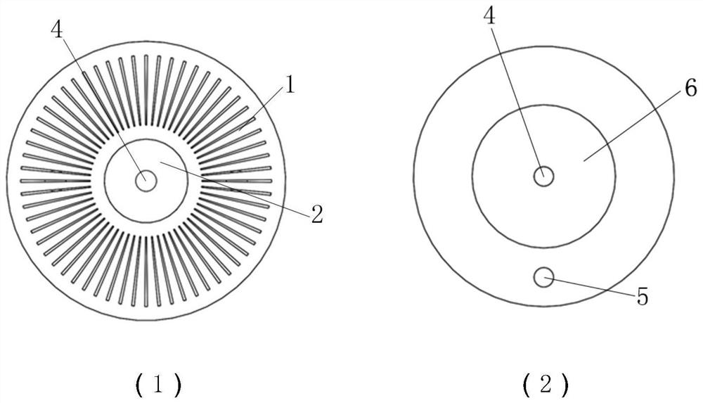
[0020] like figure 1 and figure 2 As shown, the embodiment of the present invention provides an integrated hot end structure of a pulse tube refrigerator, which includes: an annular slit body 1, a pulse tube hot end hole 2, a rectification cavity 3, a compressed gas flow channel 4, and a phase-modulating gas Runner 5 and compression chamber 6. The body of the heat exchanger is cylindrical, and from top to bottom are the annular slit body 1, the hot end hole 2 of the pulse tube, the rectification cavity 3, the compressed gas flow channel 4, the phase-modified gas flow channel 5, and the compression cavity 6. The annular slit extends radially away from the axis of the heat exchanger body and runs through the annular slit body 1. The hot end hole 2 of the pulse tube is coaxially distributed with the annular slit. The top view is as follows: ...


PUM


Abstract

The invention discloses an integrated hot end structure of a pulse tube refrigerator and an implementation method. The integrated hot end structure comprises an annular slit body, a pulse tube hot end hole, a rectifying cavity, a compressed gas flow channel, a phase modulation gas flow channel and a compression cavity. A heat exchanger body is a cylinder, an annular slit extends outwards in the radial direction away from the axis of the heat exchanger body in a radial shape and penetrates through the annular slit body, and the rectifying cavity is an annular hollow flow channel and communicates with the annular slit body; and the compressed gas flow channel and the phase modulation gas flow channel are distributed in the circumferential direction, the pulse tube hot end hole communicates with the phase modulation gas flow channel, and the compression cavity is a cylindrical cavity body and communicates with the rectifying cavity through the compressed gas flow channel. The invention further discloses the implementation method of the integrated hot end structure. According to the integrated hot end structure of the pulse tube refrigerator, the whole structure of the pulse tube refrigerator can be simplified, the weight of the whole refrigerator can be reduced, the flow loss of a pipeline can be reduced, the flocculation flow disturbance of gas in the heat exchanger can be effectively inhibited, the efficiency of the heat exchanger can be improved, and high-efficiency refrigeration can be realized.

Description

technical field [0001] The invention belongs to the field of pulse tube cryogenic refrigerators, and in particular relates to an integrated hot end structure of a pulse tube refrigerator. Background technique [0002] The pulse tube refrigerator was proposed by Gifford and Longsworth in the 1960s. It has a simple structure and high reliability, and is widely used in infrared devices, low-temperature electronic devices, superconducting magnets and other fields. The pulse tube refrigerator is composed of a driving mechanism, a connecting pipe of the driving mechanism, a hot-end heat exchanger, a regenerator, a cold-end heat exchanger, a pulse tube, a regulating connection pipe, and a phase-modulating mechanism. Heaters are arranged separately and are generally connected by gas pipelines, resulting in a large number of pipelines in the current commonly used pulse tube refrigerators, complex structure of the whole machine, large gas flow loss and weight, and a large gap in relat...

Claims


Application Information

Patent Timeline
Patent Type & Authority Applications(China)
IPC IPC(8): F25B9/14F25B39/00
CPCF25B9/145F25B39/00
Inventor 吴亦农刘少帅惠贺军蒋珍华丁磊黄政吴文萃殷旺曲晓萍杨宝玉陆志项汉桢宋键镗
Owner SHANGHAI INST OF TECHNICAL PHYSICS - CHINESE ACAD OF SCI
Why Eureka
Try Eureka